Pressure Vessel CAD Block
Horizontal vessels of 1000 l, Ø800 x 2150 mm, and 5000 l, Ø1400 x 3470 mm, on two saddles.
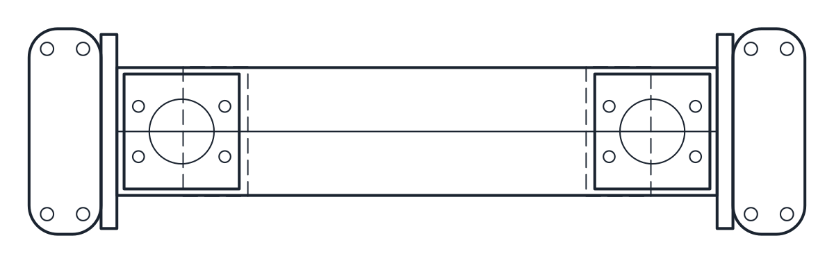
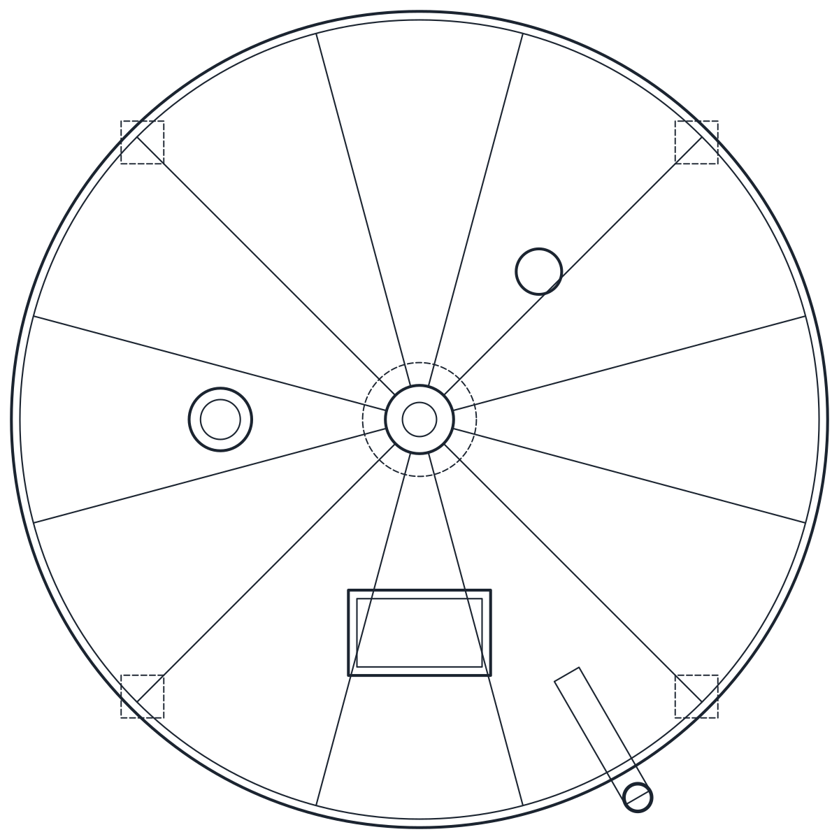
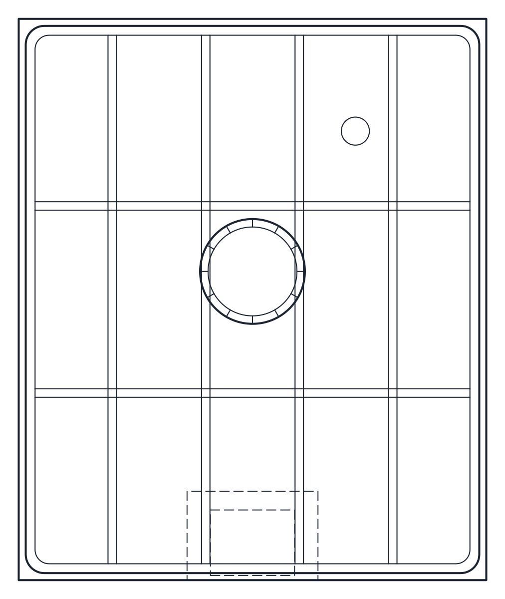
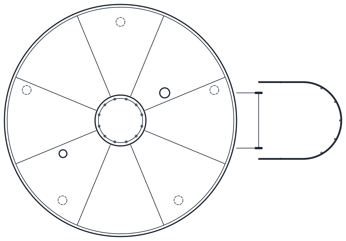
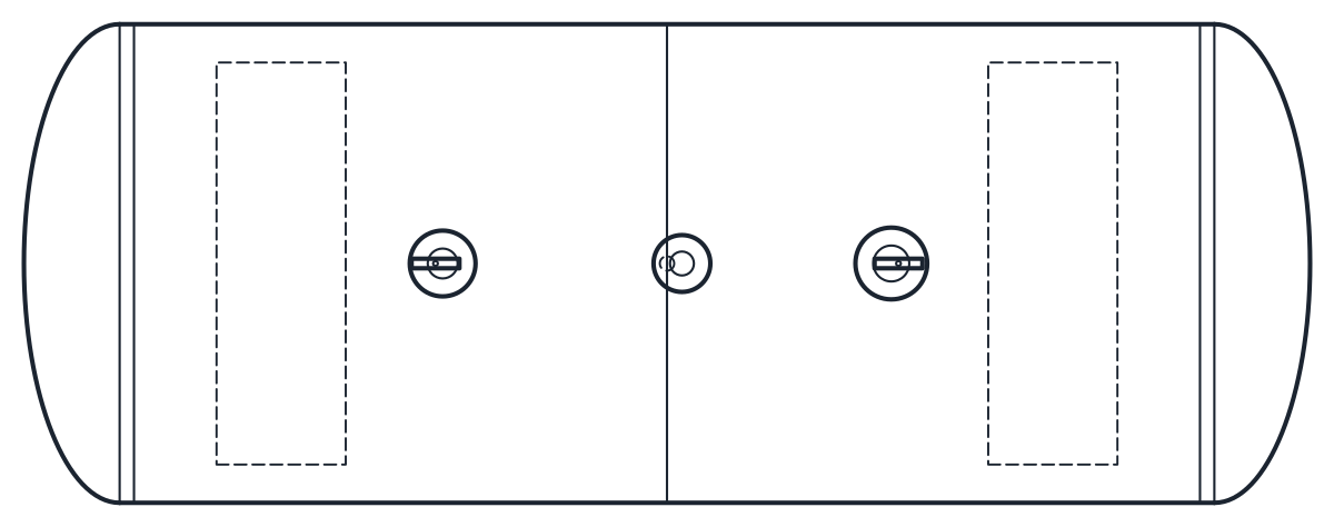
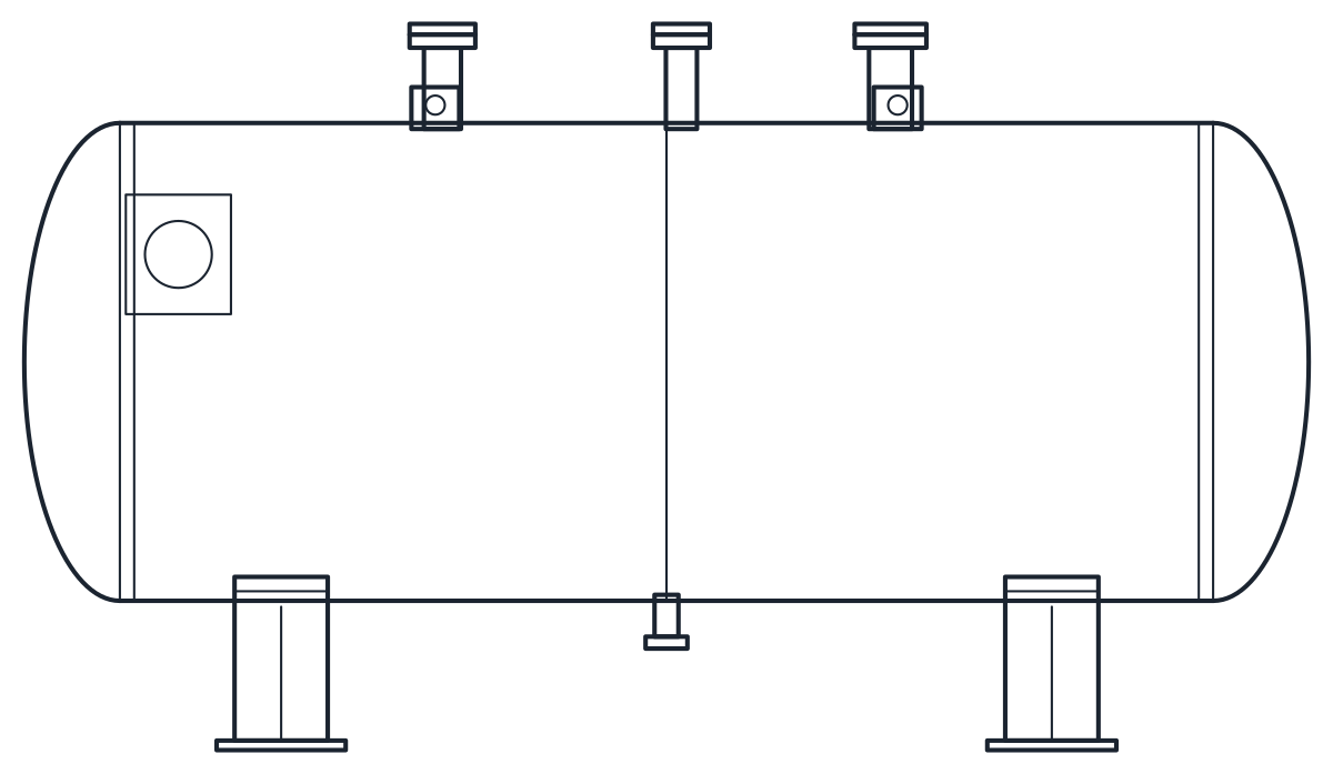
Horizontal pressure vessel 1000 l, Ø800 x 2150, torispherical heads on saddles
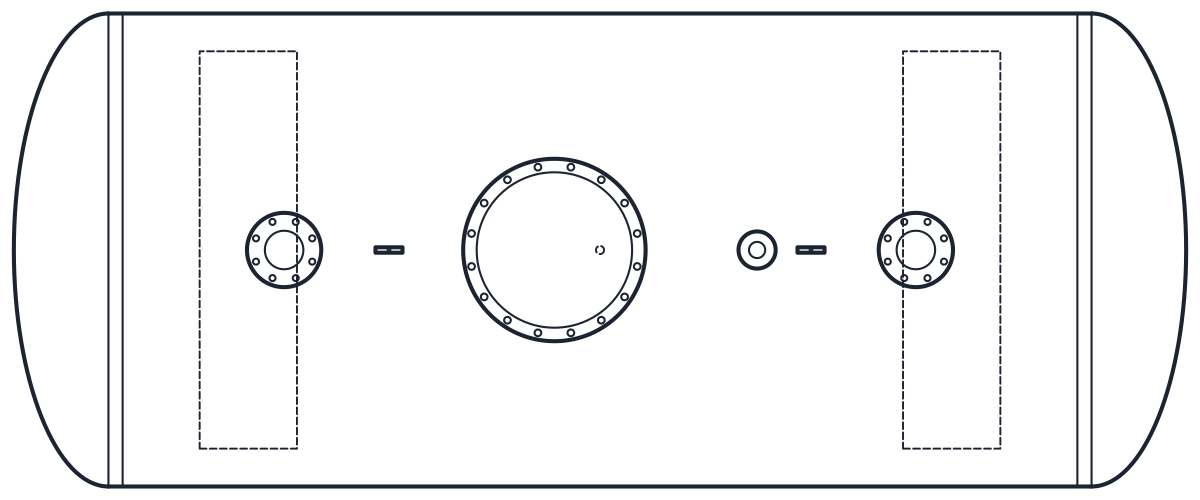
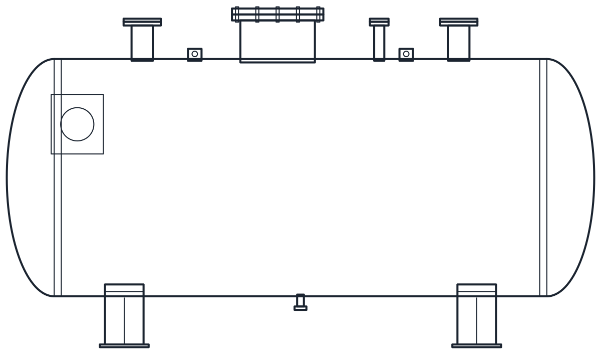
Horizontal pressure vessel 5000 l, Ø1400 x 3470, with manhole and DN100 nozzles
- Units
- Millimetres (INSUNITS 4), drawn at paper size
- Formats
- DWG 2010 · DXF R2010
- Opens in
- AutoCAD and AutoCAD LT 2010 or later, BricsCAD, ZWCAD and DraftSight. The DXF opens in most CAD programs.
- Views
- Plan view + Front elevation
- License
- Free for personal and commercial projects. License
This pressure vessel CAD block download holds two horizontal vessels with torispherical heads on saddles, each drawn in plan and elevation in millimetres in the DWG and DXF. The 1000 l vessel is Ø800 x 2150 mm. The 5000 l vessel is Ø1400 x 3470 mm and has a manhole and DN100 inlet and outlet nozzles.
Pressure vessel CAD block sizes
Both vessels use the dimensions of a typical catalogue horizontal compressed-air receiver. The 1000 l size has a diameter of 800 mm and a length of 2150 mm, a G 1 1/2 inlet, a G 2 outlet and two hand holes. The 5000 l size from the same range has a diameter of 1400 mm, a length of 3470 mm, DN100 inlet and outlet and one manhole. These are catalogue values for one product line, so check the drawing of the vessel you buy, since nozzle positions and lengths change from one maker to another.
Horizontal pressure vessel drawing in plan and elevation
The heads are drawn as torispherical heads with a depth of 0.2 x D. That is the usual proportion for this head type: about 0.1935 D plus a share of the wall thickness. The plan shows the shell and both heads from above, 2150 x 800 mm and 3470 x 1400 mm.
In the elevation each vessel sits on two saddles placed at 0.2 L from each end, which puts the saddle centres at 1290 mm on the 1000 l vessel and 2082 mm on the 5000 l vessel. The clear height under the shell is 250 mm and 300 mm. The saddle positions and the clearance are representative, because the product pages do not give them. The overall height of the elevation is 1216 mm for the small vessel and 2008 mm for the large one. Outlines are on layer M-TANK, nozzles and saddles on M-TANK-DETL and hidden lines on A-HIDN.
Using the pressure vessel block in a compressor room layout
Use the plan to reserve floor space and the elevation to check pipe heights at the inlet and outlet. Leave room in front of the manhole and the hand holes, because inspections need access to them. If the real saddles differ from the drawn ones, move the saddle lines and keep the shell, since the shell and length are the catalogue values.
On the process diagram the vessel is drawn with the horizontal vessel outline from the P&ID symbols library. For an atmospheric tank on the same site, use the storage tank CAD block.