Storage Tank CAD Block
Vertical cone-roof tanks of 10 m3, Ø2100 x 4155 mm on legs, and 50 m3, Ø3000 x 7100 mm shell, with a caged ladder.
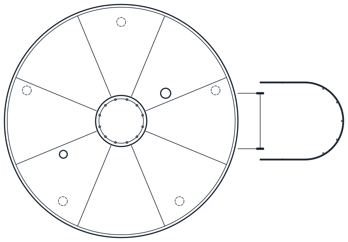
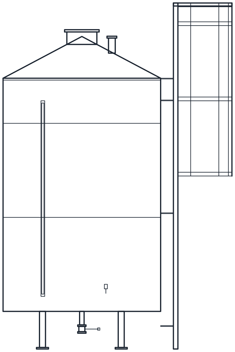
Vertical flat-bottom storage tank 10 m3, Ø2100, cone roof, on 5 legs
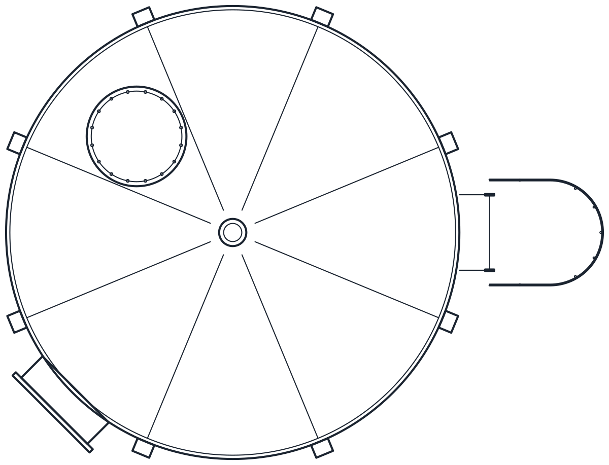
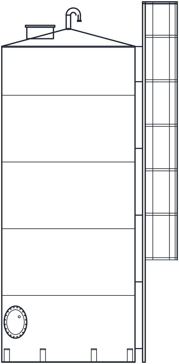
Vertical flat-bottom storage tank 50 m3, Ø3000, cone roof, anchored on slab
- Units
- Millimetres (INSUNITS 4), drawn at paper size
- Formats
- DWG 2010 · DXF R2010
- Opens in
- AutoCAD and AutoCAD LT 2010 or later, BricsCAD, ZWCAD and DraftSight. The DXF opens in most CAD programs.
- Views
- Plan view + Front elevation
- License
- Free for personal and commercial projects. License
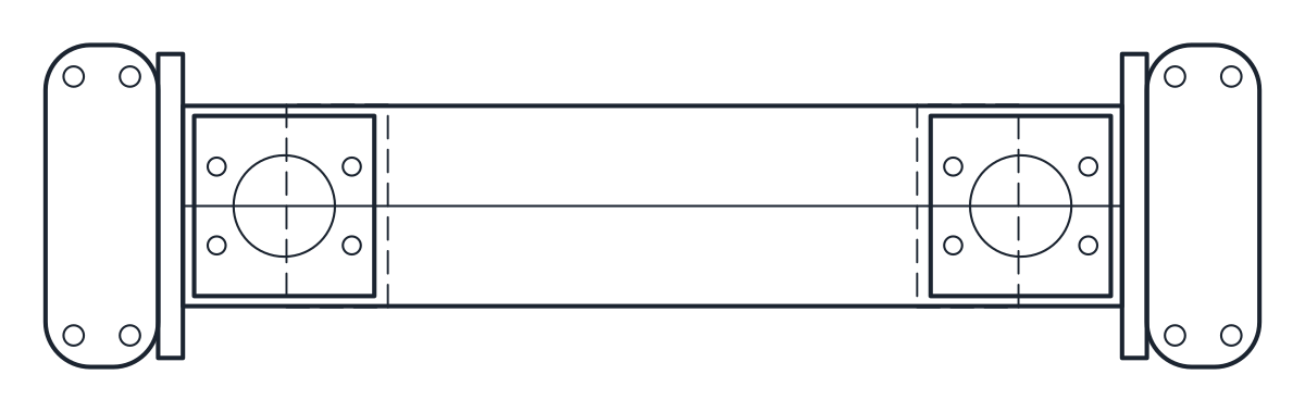
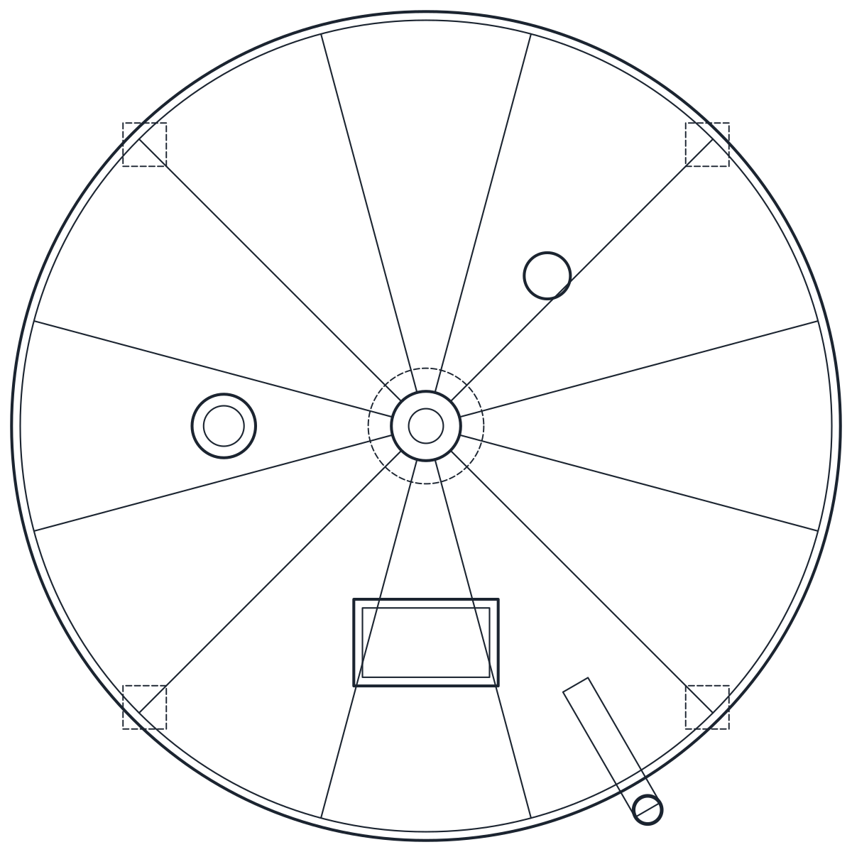
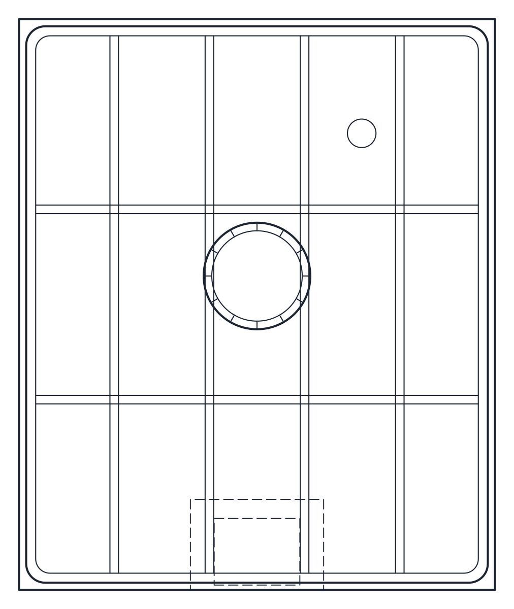
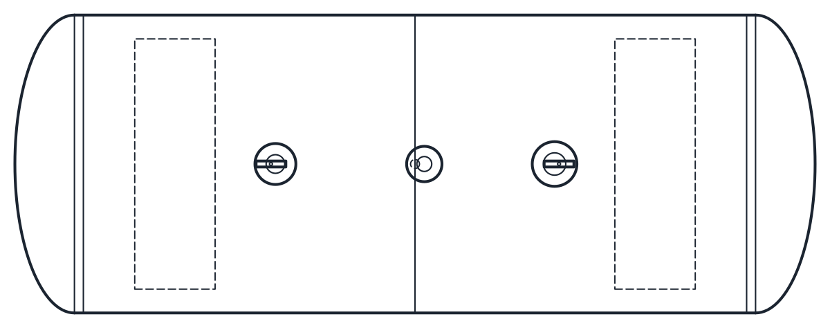
This storage tank CAD block download holds two vertical flat-bottom tanks with a cone roof, each drawn in plan and elevation in millimetres in the DWG and DXF. The first is a 10 m3 tank, Ø2100, standing on five legs. The second is a 50 m3 tank, Ø3000, anchored on a concrete slab. Both carry a fixed ladder with a safety cage, so the plan view is wider than the shell.
Storage tank DWG in 10 m3 and 50 m3
The 10 m3 tank follows a typical catalogue flat-bottom stainless storage tank with an effective diameter of 2100 mm. The 10,000 l version is 4155 mm high on five welded 500 mm feet. In the drawing that height is split into a 3100 mm shell and a cone roof that rises 555 mm. The DN400 top manhole is a representative size.
The 50 m3 tank is not a catalogue model, so treat all of its dimensions as indicative. The Ø3000 x 7100 mm shell gives 50.2 m3, the cone roof has a 15 degree slope with a 402 mm rise, and the tank has a DN600 side manway, a roof manhole and eight anchor chairs. Catalogue steel tanks of this volume are often slimmer and taller, so check the tank you order before you fix the layout.
Storage tank drawing in plan and elevation
The ladder on both tanks is drawn to the geometry of EN ISO 14122-4: rungs 200 mm off the shell, 500 mm between stiles, a cage 750 mm deep with hoops at no more than 1000 mm, and the cage starting at 2300 mm. The stiles run 1000 mm above the top of the shell. This is why the plan measures the diameter plus 950 mm, 3050 mm on the 10 m3 tank and 3950 mm on the 50 m3 one.
The elevation shows the shell, the roof, the legs or anchor chairs, the manholes and the ladder. Its overall height is set by the ladder stiles: 4600 mm for the 10 m3 tank and 8100 mm for the 50 m3 tank. Outlines are on layer M-TANK, details such as nozzles and the ladder on M-TANK-DETL, and hidden lines on A-HIDN.
Using the storage tank block in a plant layout
Place the plan with the ladder on the access side and keep that side clear of pipe racks and walls. On the 50 m3 tank the anchor chairs mark where the bolts go into the slab. If you also draw the process, the tank appears as a vessel on the flow diagram, and the P&ID symbols library has the matching outline. For bulk solids rather than liquids, see the silo CAD block.