Silo CAD Block
A 30.8 m3 steel silo, Ø2870 x 7460 mm, with a 60 degree cone, 400 mm outlet and 800 mm clearance under the cone.
Steel silo 30 m3, Ø2870, 60 degree hopper on four legs
- Units
- Millimetres (INSUNITS 4), drawn at paper size
- Formats
- DWG 2010 · DXF R2010
- Opens in
- AutoCAD and AutoCAD LT 2010 or later, BricsCAD, ZWCAD and DraftSight. The DXF opens in most CAD programs.
- Views
- Plan view + Front elevation
- License
- Free for personal and commercial projects. License
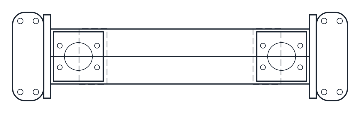
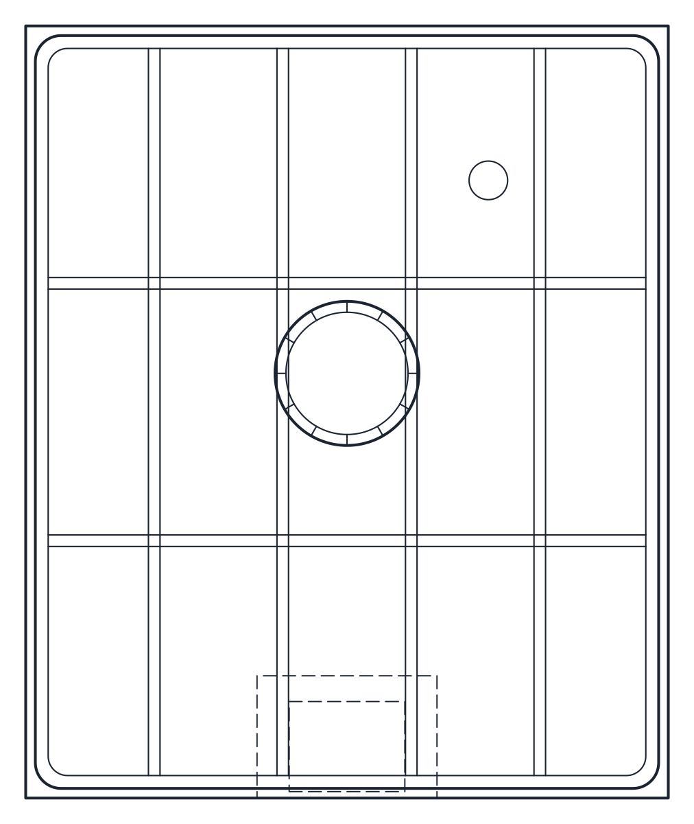
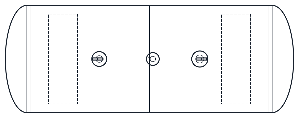
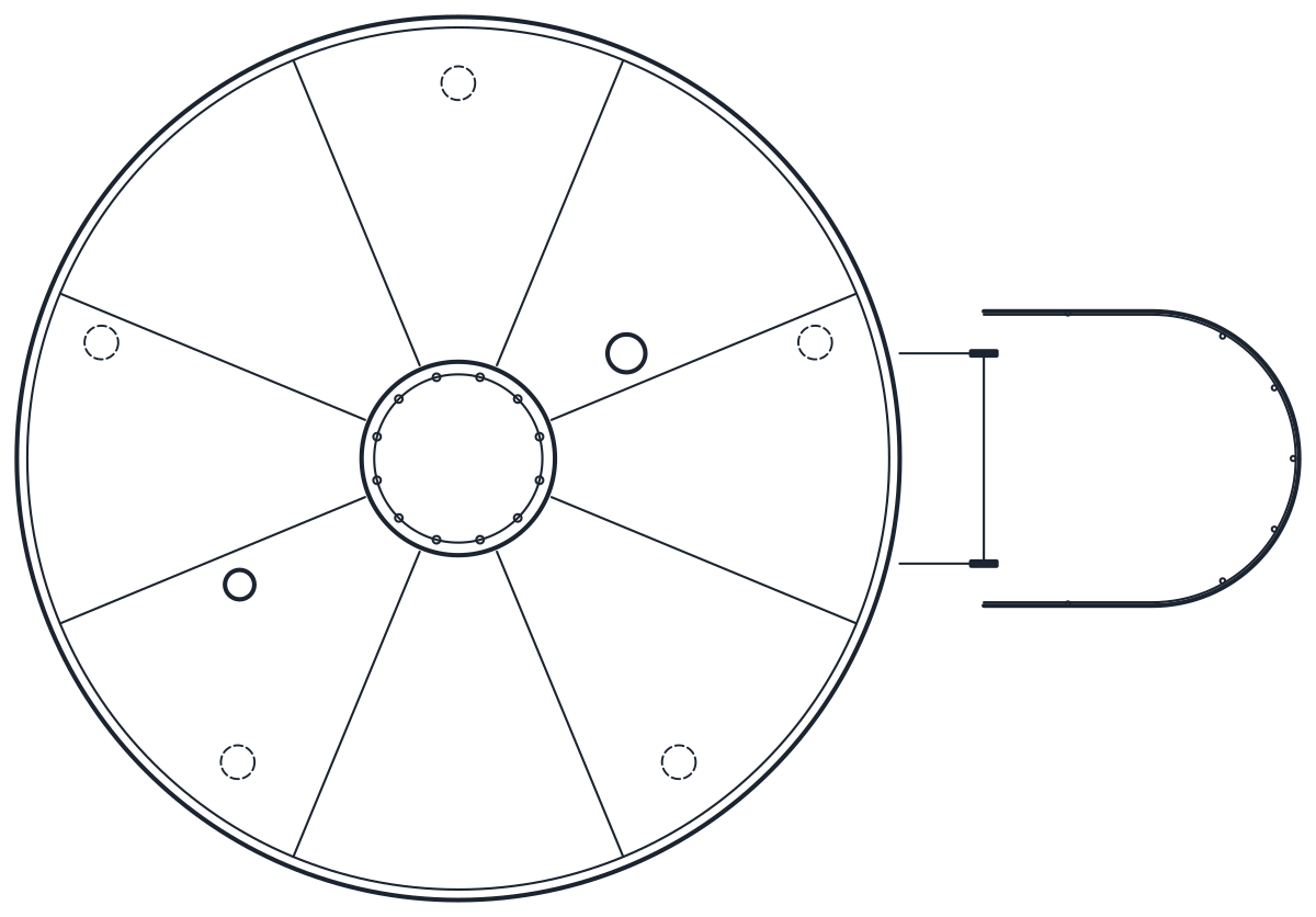
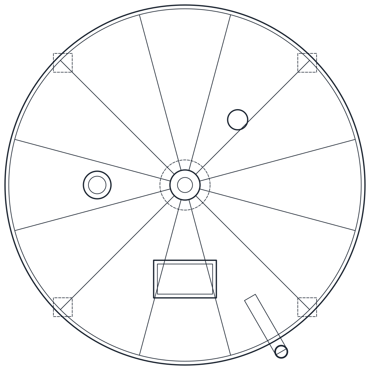
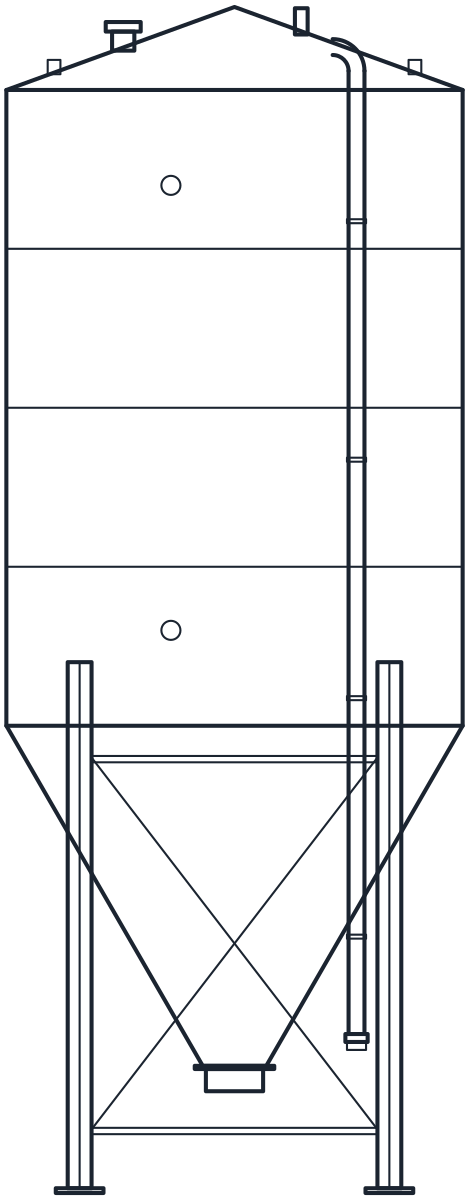
This silo CAD block download holds one 30 m3 steel silo, Ø2870, with a 60 degree hopper on four legs, drawn in plan and elevation in millimetres in the DWG and DXF. The plan is 2870 x 2870 mm and the elevation is 7460 mm high.
Silo CAD block dimensions
The silo is drawn after a typical catalogue centre-discharge silo of 30.8 m3. From the manufacturer data sheet come the barrel diameter of 2.87 m, the overall height of 7.46 m, the 60 degree cone, the 400 mm discharge aperture, the 800 mm clearance under the cone and the 3.5 x 3.5 m concrete base. The same data sheet lists an external filler pipe, a roof relief valve and an exhaust pipe, and the drawing includes them. Silo makers use their own leg and roof designs, so check the sheet of the silo you order.
Steel silo drawing in plan and elevation
With a 60 degree cone that narrows from Ø2870 to Ø400, the hopper is 2139 mm high. Add the 800 mm clearance and the barrel starts 2939 mm above the floor. The roof has a 20 degree pitch with a 522 mm rise, which leaves about 4000 mm of barrel to reach the 7460 mm overall height. The roof pitch, the leg section and the bracing are representative: the data sheet does not give them.
The plan shows the barrel, the legs and the roof fittings from above. The elevation shows the barrel, the cone, the legs with their bracing and the filler pipe up the side. Outlines are on layer M-TANK, fittings and bracing on M-TANK-DETL and hidden lines on A-HIDN.
Using the silo block on a site plan
Reserve the 3.5 x 3.5 m base on the site plan, not just the barrel circle, because the base is what the civil works have to build. The 800 mm under the cone is the space for the discharge equipment, such as a valve and a screw conveyor, so check that what you plan to fit there is not taller. Keep the filler pipe on the side where the delivery vehicle can park.
On the process diagram the silo is drawn as a vessel, and the P&ID symbols library has the outlines. For liquids stored on the same site, see the storage tank CAD block.