Pneumatic Symbols
Pneumatic circuit symbols after ISO 1219-1: air preparation, valves and their actuators, cylinders and logic valves.
Pneumatic Symbols library
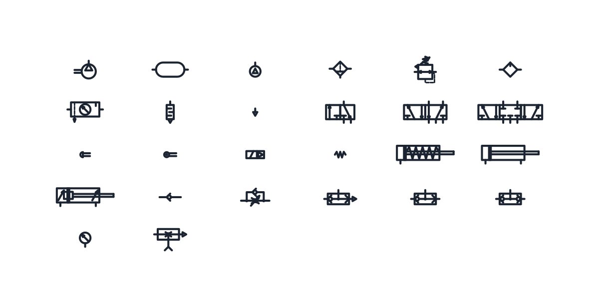
Air supply and FRL symbols
-
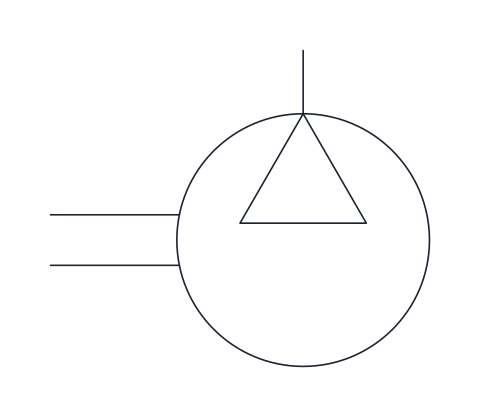
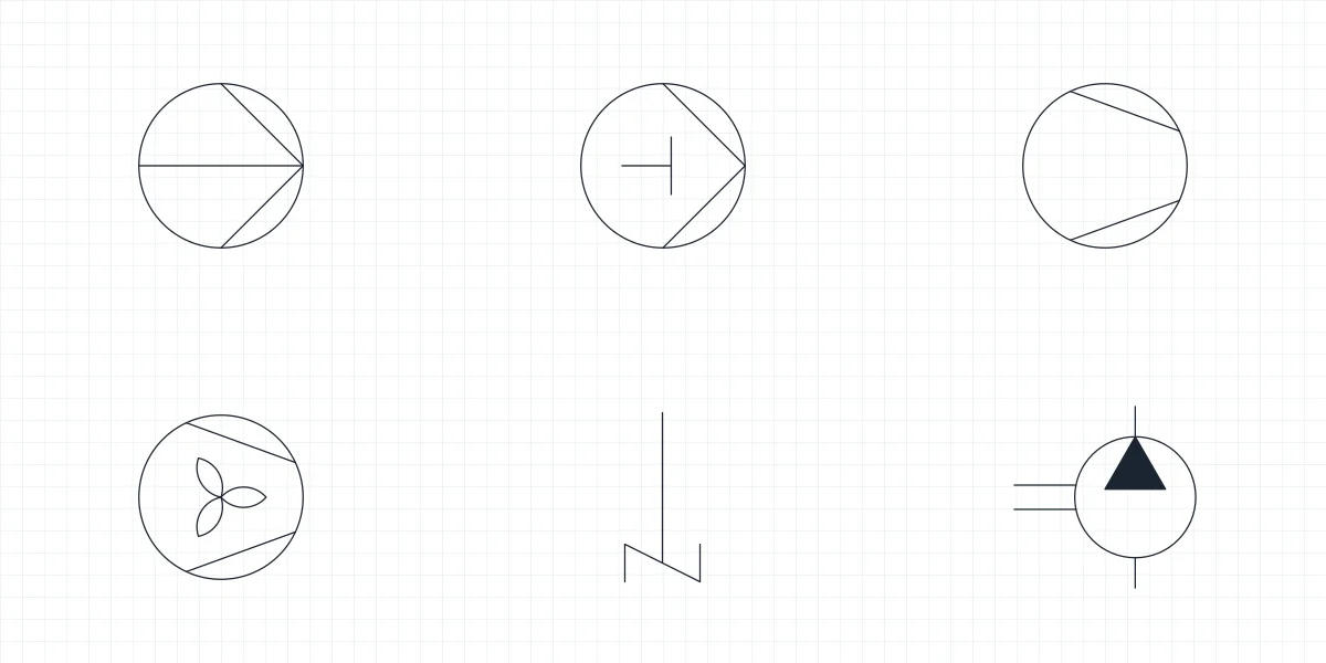
Compressor
Circle with an open triangle pointing to the outlet and a drive shaft, representing the machine that compresses atmospheric air. It starts the air supply section of a pneumatic diagram.
IND_PNEUMATIC_SYMBOLS_COMPRESSOR
-
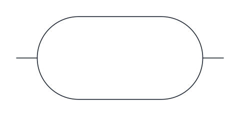
Air receiver
Horizontal capsule for the pressure vessel that stores compressed air and evens out demand peaks. Drawn between the compressor and the distribution network.
IND_PNEUMATIC_SYMBOLS_AIR_RECEIVER
-
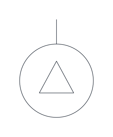
Pneumatic pressure source
Small circle with an open triangle that stands for the compressed air supply without detailing the compressor plant. Use it at the supply port of machine-level circuits.
IND_PNEUMATIC_SYMBOLS_PRESSURE_SOURCE
-
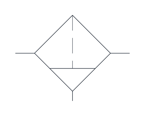
Air filter with manual drain
Square on its corner with a dashed filter element, a condensate bowl and a manual drain at the bottom. It removes particles and water before the air reaches valves and cylinders.
IND_PNEUMATIC_SYMBOLS_AIR_FILTER
-
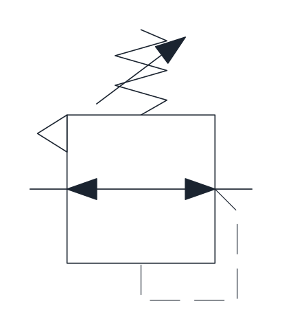
Pressure regulator, relieving
Adjustable regulator that keeps outlet pressure, sensed through the dashed line, at the spring setting and vents excess downstream pressure through its exhaust. Fitted after the filter in the air preparation unit.
IND_PNEUMATIC_SYMBOLS_PRESSURE_REGULATOR
-
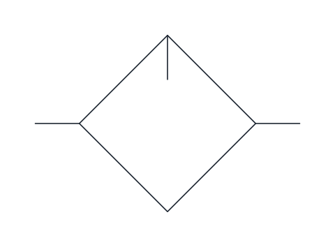
Lubricator
Square on its corner with a short line from the top corner, for the device that adds oil mist to the air stream. Only needed where the connected components require lubricated air.
IND_PNEUMATIC_SYMBOLS_LUBRICATOR
-
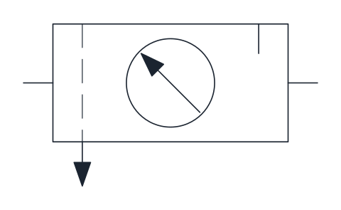
FRL unit, simplified
Single rectangle combining filter, regulator with gauge and lubricator, with the condensate drain below. Use it in machine diagrams where the air preparation unit does not need to be shown in detail.
IND_PNEUMATIC_SYMBOLS_FRL_UNIT
Exhaust and silencer symbols
-
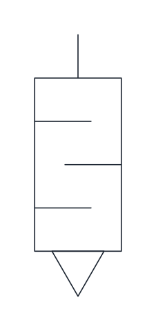
Silencer
Rectangle with internal baffles and an exhaust triangle, fitted to a valve exhaust port to reduce noise. Hangs from the port it serves.
IND_PNEUMATIC_SYMBOLS_SILENCER
-
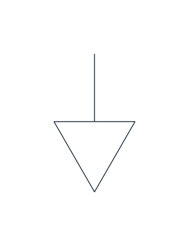
Exhaust port
Open triangle pointing away from the valve, for a port that vents directly to atmosphere without a connection. Attach it below exhaust ports 3 and 5.
IND_PNEUMATIC_SYMBOLS_EXHAUST_PORT
Pneumatic directional control valve symbols
-
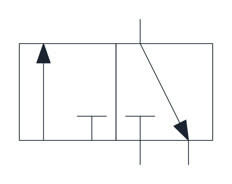
3/2 directional control valve
Three-port, two-position valve shown normally closed: at rest port 2 exhausts to 3 and supply 1 is blocked, when actuated 1 feeds 2. Used for single-acting cylinders and signal generation.
IND_PNEUMATIC_SYMBOLS_DCV_3_2
-
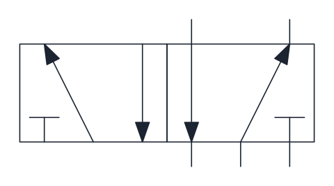
5/2 directional control valve
Five-port, two-position valve with two outputs and two exhausts; supply 1 switches between outputs 2 and 4. The standard valve for double-acting pneumatic cylinders.
IND_PNEUMATIC_SYMBOLS_DCV_5_2
-
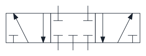
5/3 directional control valve, closed centre
Three-position valve whose centre position blocks all five ports, trapping air in both cylinder chambers. Used to stop a cylinder in mid-stroke.
IND_PNEUMATIC_SYMBOLS_DCV_5_3_CLOSED_CENTRE
Pneumatic valve actuator symbols
-
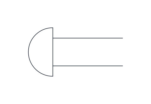
Push-button actuator
Manual operation by a push button, drawn as the operating stem capped with a rounded head. Usually paired with a return spring.
IND_PNEUMATIC_SYMBOLS_ACTUATOR_PUSHBUTTON
-
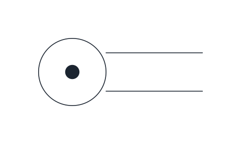
Roller actuator
Mechanical operation by a roller on the end of the plunger, drawn as a circle with a centre dot. Used for limit valves that a moving cam or machine part actuates.
IND_PNEUMATIC_SYMBOLS_ACTUATOR_ROLLER
-
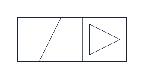
Solenoid with pilot actuation
Solenoid that switches an internal pilot stage, which then shifts the main valve with air pressure, drawn as the coil next to a box with an open triangle. The usual operator on solenoid valves for larger flows.
IND_PNEUMATIC_SYMBOLS_ACTUATOR_SOLENOID_PILOT
-
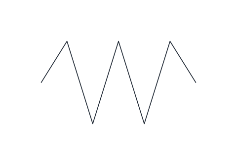
Return spring
Zigzag spring that returns the valve to its rest position. Drawn for the right-hand side of the valve; mirror it for the left.
IND_PNEUMATIC_SYMBOLS_ACTUATOR_SPRING
Pneumatic cylinder symbols
-
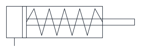
Single-acting cylinder, spring return
Cylinder with one supply port and a spring that retracts the piston when the air is exhausted. Used for short strokes such as clamping and ejecting.
IND_PNEUMATIC_SYMBOLS_SINGLE_ACTING_CYLINDER
-
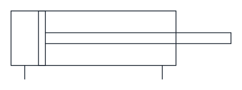
Double-acting cylinder
Cylinder with a port at each end, so compressed air both extends and retracts the rod. The most common pneumatic linear actuator.
IND_PNEUMATIC_SYMBOLS_DOUBLE_ACTING_CYLINDER
-
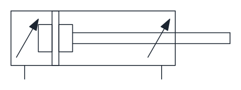
Double-acting cylinder, adjustable cushioning
Double-acting cylinder with cushioning on both sides of the piston, the oblique arrows showing that the cushioning is adjustable. It slows the piston near the end of stroke to reduce impact.
IND_PNEUMATIC_SYMBOLS_DOUBLE_ACTING_CYLINDER_CUSHIONED
Check and logic valve symbols
-
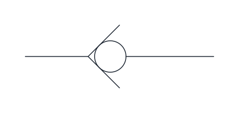
Check valve
Ball against a seat that lets air pass from left to right and blocks the reverse direction. Used to hold pressure in a branch or keep flow one-way.
IND_PNEUMATIC_SYMBOLS_CHECK_VALVE
-
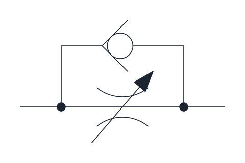
One-way flow control valve
Adjustable throttle with a check valve in parallel, restricting flow in one direction only. Fitted at cylinder ports to set the piston speed, usually by throttling the exhaust air.
IND_PNEUMATIC_SYMBOLS_ONE_WAY_FLOW_CONTROL_VALVE
-
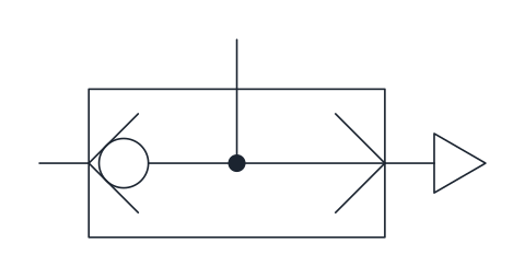
Quick exhaust valve
Ball valve that feeds the outlet from the inlet and, when the inlet drops, vents the outlet straight to atmosphere. Mounted close to a cylinder port to increase piston speed.
IND_PNEUMATIC_SYMBOLS_QUICK_EXHAUST_VALVE
-
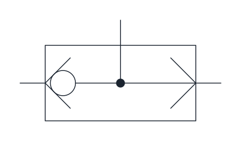
Shuttle valve (OR)
Valve with two inlets and one outlet in which a single ball closes the inlet with the lower pressure. Gives an OR function, for example to operate a cylinder from two different points.
IND_PNEUMATIC_SYMBOLS_SHUTTLE_VALVE
-
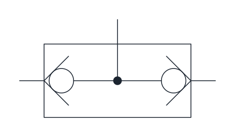
Two-pressure valve (AND)
Valve with two inlets and one outlet that passes a signal only when both inlets are pressurised. Used for AND logic such as two-hand safety controls.
IND_PNEUMATIC_SYMBOLS_TWO_PRESSURE_VALVE
Gauge and vacuum symbols
-
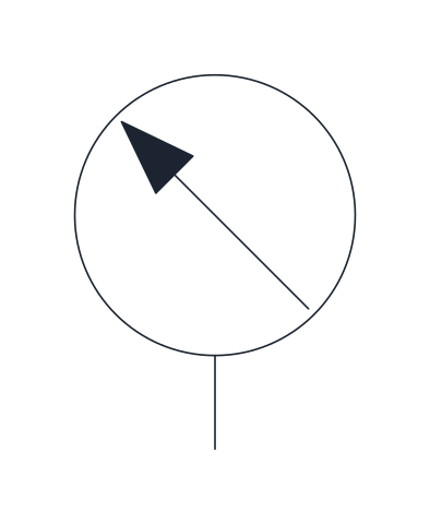
Pressure gauge
Measuring instrument circle with an oblique pointer arrow, connected to the line whose pressure it displays. Typically drawn at the regulator outlet.
IND_PNEUMATIC_SYMBOLS_PRESSURE_GAUGE
-
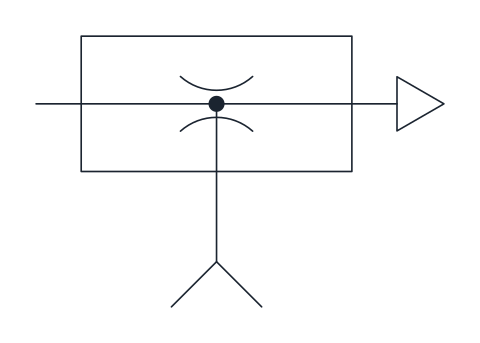
Vacuum generator (ejector)
Ejector in which supply air flows through a nozzle and creates vacuum at the side port, with the air exhausting on the right. Used to feed vacuum cups for handling parts.
IND_PNEUMATIC_SYMBOLS_VACUUM_GENERATOR
- Units
- Millimetres (INSUNITS 4), drawn at paper size
- Formats
- DWG 2010 · DXF R2010 · PDF
- Opens in
- AutoCAD and AutoCAD LT 2010 or later, BricsCAD, ZWCAD and DraftSight. The DXF opens in most CAD programs.
- Views
- Sheet
- License
- Free for personal and commercial projects. License
These pneumatic symbols follow the ISO 1219-1 conventions for compressed air circuits: the air supply and its preparation, directional valves with their actuators, cylinders and the logic valves used in pneumatic control. Every symbol is a named block in the DWG and DXF, and the PDF sheet prints the complete chart of pneumatic symbols.
Pneumatic symbols and hydraulic symbols: the difference
Pneumatics and hydraulics share the same graphic language, with one visible difference: the energy triangle on pumps, compressors and motors is hollow for air and filled for oil. Pneumatic circuits also show exhausts, because the air leaves the valve to the atmosphere instead of returning to a tank, and an exhaust port or a silencer appears on almost every valve.
How to read pneumatic valve symbols
A valve is a row of squares, one per position, and the arrows inside each square show the air path in that position. The shorthand counts ports and positions: a 5/2 valve has five ports and two positions, a 3/2 valve has three ports and two positions. Most pneumatic valves number their ports: 1 for the supply, 2 and 4 for the outputs, 3 and 5 for the exhausts. The square that touches the lines is the position the valve takes at rest.
The actuators are separate blocks: push button, roller, spring and solenoid with pilot. Place one at each end of a valve to show what switches it and what brings it back.
Air preparation symbols: filter, regulator and lubricator
Before compressed air reaches the valves it is filtered, regulated and, in some installations, lubricated. The library has each element as its own symbol and the combined FRL unit, plus the compressor, the air receiver, the pressure source and the pressure gauge.
Pneumatic cylinder and logic valve symbols
Cylinders come single-acting, double-acting and double-acting with adjustable cushioning. For control logic, the shuttle valve passes air from either of two inputs and works as an OR, while the two-pressure valve only passes air when both inputs are present and works as an AND. The quick exhaust valve, the one-way flow control valve and the vacuum generator complete the set.
Drawing a pneumatic circuit with these blocks
The symbols are drawn at paper size on a 2.5 mm grid. Valve squares are 10 x 10 mm, and 15 mm wide on five-port valves. The base point sits on a port, port 1 of the rest position on directional valves, so lines on the same grid connect directly. In AutoCAD, insert them from DesignCenter (ADCENTER); in other programs, open the DXF and copy the blocks. The DWG is saved for AutoCAD 2010 and later.
ISO 1219-1 is sold by ISO and is not reproduced here. The symbols are our own drawings of its conventions, and valve makers sometimes add details of their own to their catalogue symbols.
Pneumatic valve symbol libraries
- Directional Control Valve Symbols: Hydraulic and pneumatic directional control valves, from 2/2 to 5/3, with seven actuators placed by a fixed corner.
- Check Valve Symbols: The check valve as drawn on a P&ID and in hydraulic and pneumatic circuits, with the valves that carry a check element.