Pump Symbol
Centrifugal and reciprocating pumps, compressor, fan and agitator for P&IDs, plus the hydraulic pump and pneumatic compressor.
Pump symbol library
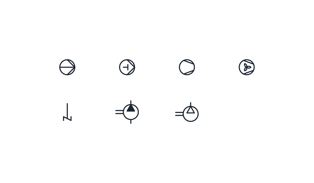
P&ID symbols
-
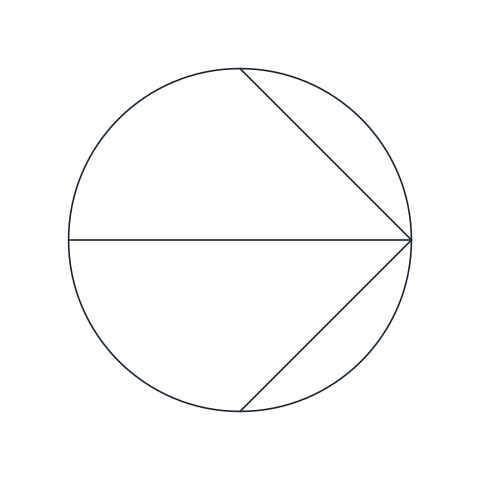
Centrifugal pump
Circle with two lines converging on the discharge side and a horizontal diameter, the centrifugal variant of the liquid pump. Rotate the block so the converging point faces the discharge.
IND_PID_SYMBOLS_CENTRIFUGAL_PUMP
-
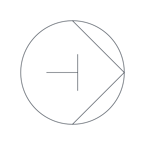
Positive displacement pump (reciprocating)
Liquid pump outline with a piston and rod drawn inside, the reciprocating positive displacement form. Suitable for metering, dosing and high-pressure duties.
IND_PID_SYMBOLS_POSITIVE_DISPLACEMENT_PUMP
-
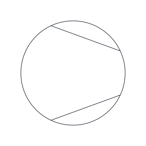
Compressor
Circle with two chords that narrow towards the outlet, the general symbol for a gas compressor or vacuum pump. The narrow end faces the high-pressure side.
IND_PID_SYMBOLS_COMPRESSOR
-
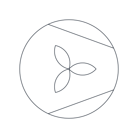
Fan or blower
Compressor-style circle with a three-blade impeller inside, for fans and blowers moving gas at low pressure rise such as ventilation, combustion air or drying air.
IND_PID_SYMBOLS_FAN_BLOWER
-
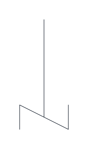
Agitator
Vertical shaft ending in an angled blade, the general stirrer symbol. Insert it at the top of a vessel so the shaft enters through the head; the base point is the top of the shaft.
IND_PID_SYMBOLS_AGITATOR
Hydraulic symbols
-
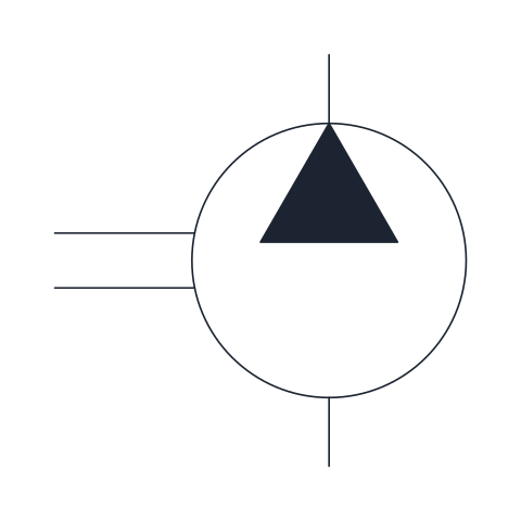
Fixed displacement hydraulic pump
Pump that delivers the same volume per revolution, drawn as a circle with a filled triangle pointing to the outlet and the drive shaft on the side. Use it for the power unit of simple circuits where flow only changes with shaft speed.
IND_HYDRAULIC_SYMBOLS_HYDRAULIC_PUMP_FIXED
Pneumatic symbols
-
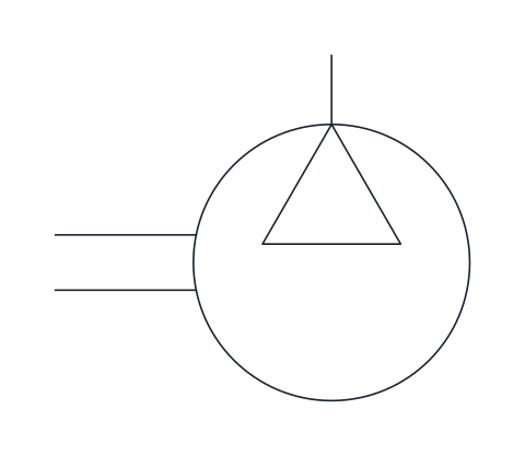
Compressor
Circle with an open triangle pointing to the outlet and a drive shaft, representing the machine that compresses atmospheric air. It starts the air supply section of a pneumatic diagram.
IND_PNEUMATIC_SYMBOLS_COMPRESSOR
- Units
- Millimetres (INSUNITS 4), drawn at paper size
- Formats
- DWG 2010 · DXF R2010 · PDF
- Opens in
- AutoCAD and AutoCAD LT 2010 or later, BricsCAD, ZWCAD and DraftSight. The DXF opens in most CAD programs.
- Views
- Sheet
- License
- Free for personal and commercial projects. License
This download brings together the pump symbol in seven forms: the centrifugal pump and the reciprocating positive displacement pump of a P&ID, the process compressor, the fan or blower and the agitator, plus the hydraulic pump and the pneumatic compressor of fluid power diagrams. That is 7 named blocks in DWG and DXF and a PDF sheet. Each one keeps the name it has in its full library, for example IND_PID_SYMBOLS_CENTRIFUGAL_PUMP or IND_HYDRAULIC_SYMBOLS_HYDRAULIC_PUMP_FIXED.
Centrifugal pump symbol
The P&ID pump is a 10 mm circle with two lines that run from the top and bottom of the circle to a point on the right, the discharge side. The centrifugal version adds a horizontal diameter. The base point is the centre of the circle, so rotate or mirror the block until the converging point faces the discharge line, with the suction coming in on the opposite side.
Positive displacement pump symbol
The positive displacement pump uses the same outline with a piston and rod drawn inside, which is the reciprocating form. Use it for metering, dosing and high-pressure duties. The block is named after the reciprocating type because that is what it shows. A gear or screw pump needs the form your project legend gives for it.
Compressor symbol and fan symbol
The process compressor is a circle with two chords that narrow towards the outlet without meeting, and the narrow end faces the high-pressure side. The same symbol stands for a vacuum pump. The fan or blower keeps that outline and adds a three-blade impeller, for gas moved at a low pressure rise such as ventilation, combustion air or drying air. Both are placed by their centre.
The agitator is not a pump but it shares the rotating equipment group. It is a vertical shaft with an angled blade, and its base point is the top of the shaft, so it sits on the head of a vessel. The vessels and exchangers it goes with are on the heat exchanger symbol page.
Pump symbols in hydraulic and pneumatic diagrams
Fluid power diagrams follow other rules. The hydraulic pump is a circle with a filled triangle pointing out at the delivery port, its base point on the suction connection below. The pneumatic compressor has a hollow triangle and its base point on the outlet at the top, with the circle hanging below. Both have the drive shaft on the left. Use these two in machine circuit diagrams and keep the P&ID forms for process drawings, so each sheet speaks one symbol language. The pump with its motor, relief valve and tank is described on the hydraulic pump symbol page, and the full process set is the P&ID symbols library.
The process symbols are our own drawings after ISO 10628-2, and the two fluid power symbols after ISO 1219-1. You can buy both standards from ISO; they are not copied here.