Hydraulic Symbols
Hydraulic circuit symbols after ISO 1219-1, from pumps and cylinders to 4/3 valves and their actuators.
Hydraulic Symbols library
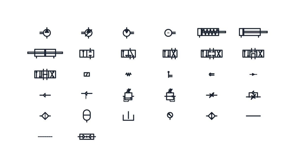
Hydraulic pump and motor symbols
-
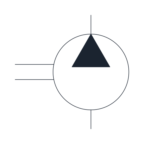
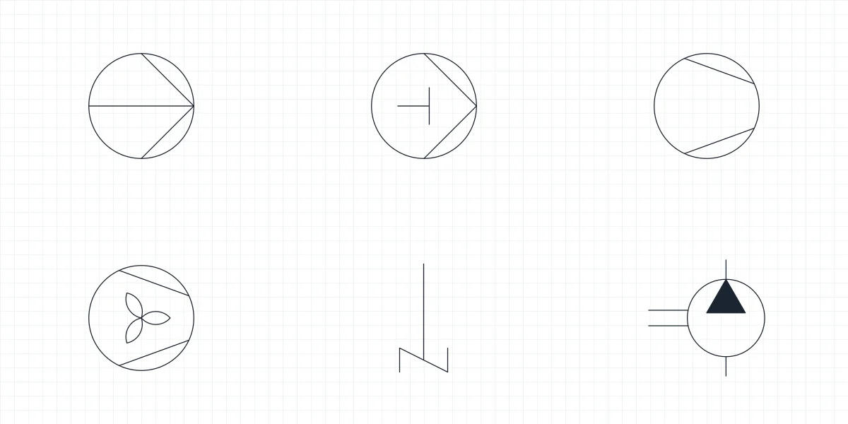
Fixed displacement hydraulic pump
Pump that delivers the same volume per revolution, drawn as a circle with a filled triangle pointing to the outlet and the drive shaft on the side. Use it for the power unit of simple circuits where flow only changes with shaft speed.
IND_HYDRAULIC_SYMBOLS_HYDRAULIC_PUMP_FIXED
-
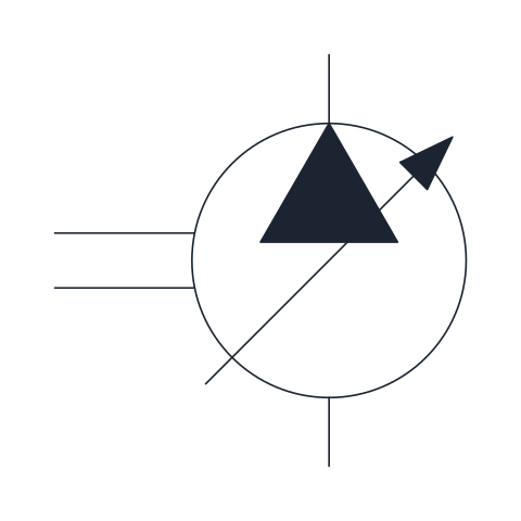
Variable displacement hydraulic pump
Pump whose displacement can be adjusted, shown by the oblique arrow across the circle. It appears in circuits that match flow to demand, such as pressure-compensated or load-sensing systems.
IND_HYDRAULIC_SYMBOLS_HYDRAULIC_PUMP_VARIABLE
-
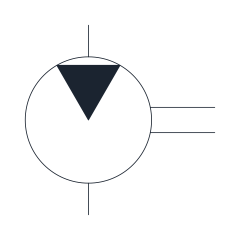
Fixed displacement hydraulic motor
Rotary actuator that turns fluid flow into shaft rotation; the filled triangle points inward at the inlet. Draw it wherever the circuit drives a winch, conveyor or wheel.
IND_HYDRAULIC_SYMBOLS_HYDRAULIC_MOTOR_FIXED
-
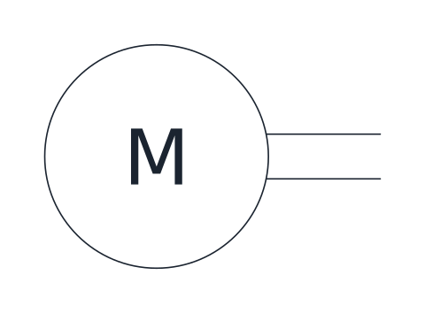
Electric motor (prime mover)
Circle with the letter M and an output shaft, representing the electric motor that drives a pump. Place it next to the pump so the two shafts meet.
IND_HYDRAULIC_SYMBOLS_ELECTRIC_MOTOR_DRIVE
Hydraulic cylinder symbols
-
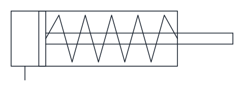
Single-acting cylinder, spring return
Cylinder with one pressure port on the cap end and a spring in the rod chamber that retracts the piston. Used where force is needed in one direction only, such as clamping or lifting.
IND_HYDRAULIC_SYMBOLS_SINGLE_ACTING_CYLINDER
-
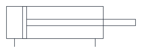
Double-acting cylinder
Cylinder with a port at each end, so pressure both extends and retracts the rod. It is the standard linear actuator in hydraulic circuits.
IND_HYDRAULIC_SYMBOLS_DOUBLE_ACTING_CYLINDER
-
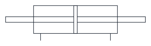
Double-rod cylinder
Double-acting cylinder with the rod passing through both end caps, giving equal effective areas on both sides of the piston. Common in steering and positioning drives that need the same speed and force in both directions.
IND_HYDRAULIC_SYMBOLS_DOUBLE_ROD_CYLINDER
Hydraulic directional control valve symbols
-
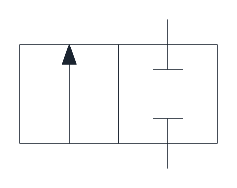
2/2 directional control valve
Two-port, two-position valve shown normally closed, with flow from P to A in the actuated position. Works as an on/off valve; add the actuator and return spring blocks beside the boxes.
IND_HYDRAULIC_SYMBOLS_DCV_2_2
-
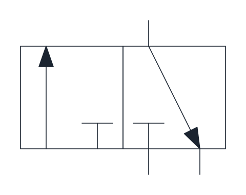
3/2 directional control valve
Three-port, two-position valve shown normally closed: at rest A is connected to tank and P is blocked, when actuated P feeds A. Typical for single-acting cylinders and pilot signals.
IND_HYDRAULIC_SYMBOLS_DCV_3_2
-
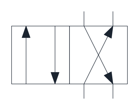
4/2 directional control valve
Four-port, two-position valve that switches P and T between ports A and B, so a double-acting cylinder extends or retracts. Ports are drawn on the right-hand box, the rest position.
IND_HYDRAULIC_SYMBOLS_DCV_4_2
-
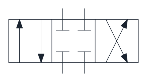
4/3 directional control valve, closed centre
Three-position valve whose centre position blocks P, T, A and B, holding the actuator in place. Suited to circuits where several valves share one pump with an accumulator or a pressure-compensated pump.
IND_HYDRAULIC_SYMBOLS_DCV_4_3_CLOSED_CENTRE
-
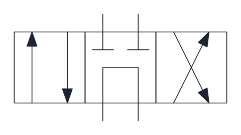
4/3 directional control valve, tandem centre
Three-position valve whose centre connects P to T and blocks A and B, so the pump unloads to tank while the actuator stays locked. A common choice with fixed displacement pumps.
IND_HYDRAULIC_SYMBOLS_DCV_4_3_TANDEM_CENTRE
-
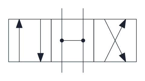
4/3 directional control valve, open centre
Three-position valve whose centre position connects all four ports, unloading the pump and leaving the actuator free to move. Used where the load may float when the valve is in neutral.
IND_HYDRAULIC_SYMBOLS_DCV_4_3_OPEN_CENTRE
Hydraulic valve actuator symbols
-
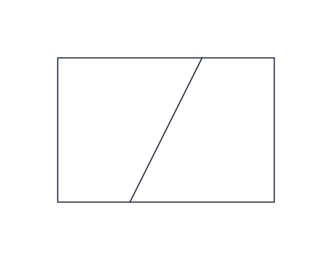
Solenoid actuator
Rectangle with an oblique line for direct electrical operation by a single winding. Attach it to the outer side of the end box it shifts.
IND_HYDRAULIC_SYMBOLS_ACTUATOR_SOLENOID
-
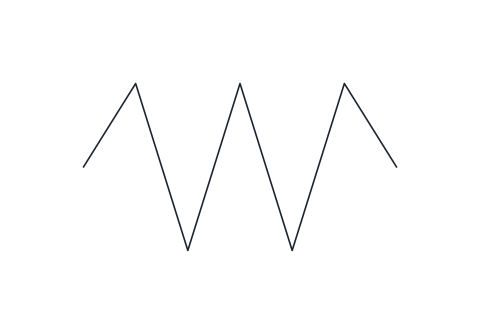
Return spring
Zigzag spring that returns the valve to its rest position when the other actuator releases. Drawn for the right-hand side of the valve; mirror it for the left.
IND_HYDRAULIC_SYMBOLS_ACTUATOR_SPRING
-
Lever actuator
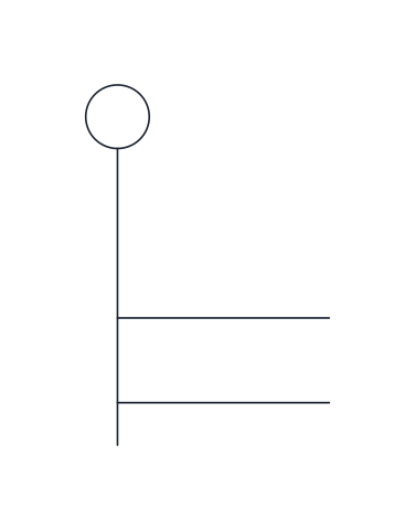
Manual operation by a hand lever, shown as the operating stem with a lever ending in a small circle. Used on mobile and manually operated valves.
IND_HYDRAULIC_SYMBOLS_ACTUATOR_LEVER
-
Push-button actuator
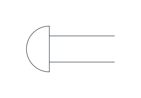
Manual operation by a push button, drawn as the operating stem capped with a rounded head. Usually combined with a return spring on the opposite side.
IND_HYDRAULIC_SYMBOLS_ACTUATOR_PUSHBUTTON
-
Hydraulic pilot actuator
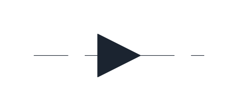
Direct pilot operation: a dashed pilot line with a filled triangle pointing at the valve shows that pilot pressure shifts the spool. Used when another valve or a pressure signal controls the main valve.
IND_HYDRAULIC_SYMBOLS_ACTUATOR_PILOT
Check valve and flow control symbols
-
Check valve
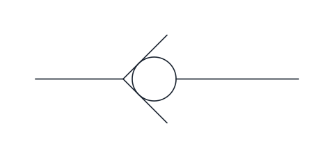
Ball pressed against a seat that lets flow pass from left to right and blocks the reverse direction. Draw it wherever the circuit must stop back-flow, for example at a pump outlet.
IND_HYDRAULIC_SYMBOLS_CHECK_VALVE
-
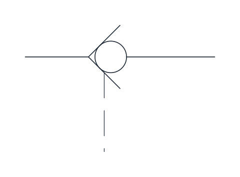
Pilot-operated check valve
Check valve that a pilot signal, drawn as the dashed line at the seat, can open to allow reverse flow. It holds a cylinder load without leakage until the pilot line is pressurised.
IND_HYDRAULIC_SYMBOLS_PILOT_OPERATED_CHECK_VALVE
-
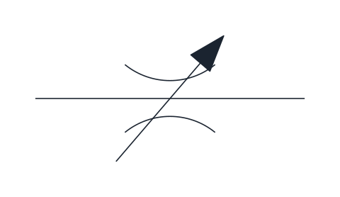
Throttle valve, adjustable
Adjustable restriction on the line, shown by two facing arcs crossed by an oblique arrow. It controls flow in both directions, so actuator speed depends on the load.
IND_HYDRAULIC_SYMBOLS_THROTTLE_VALVE
-
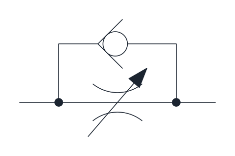
One-way flow control valve
Adjustable throttle with a check valve in parallel: flow is restricted in one direction and passes freely through the check valve in the other. The usual way to set the speed of a cylinder in one stroke only.
IND_HYDRAULIC_SYMBOLS_ONE_WAY_FLOW_CONTROL_VALVE
Pressure valve symbols
-
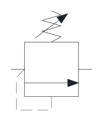
Pressure relief valve
Normally closed valve with an adjustable spring: inlet pressure, sensed through the dashed pilot line, opens the path to tank once it overcomes the spring. It sets the maximum pressure of the circuit.
IND_HYDRAULIC_SYMBOLS_PRESSURE_RELIEF_VALVE
-
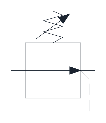
Pressure reducing valve
Normally open valve that throttles flow to keep the outlet pressure, sensed through the dashed pilot line, at the spring setting. Used to feed a branch that needs lower pressure than the main supply.
IND_HYDRAULIC_SYMBOLS_PRESSURE_REDUCING_VALVE
Filter, accumulator and reservoir symbols
-
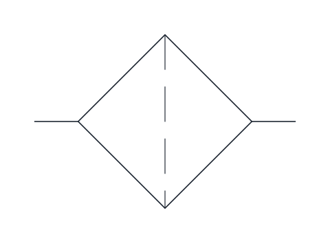
Filter
Square set on its corner with the dashed filter element across the flow path. Place it in the suction, pressure or return line depending on what it protects.
IND_HYDRAULIC_SYMBOLS_FILTER
-
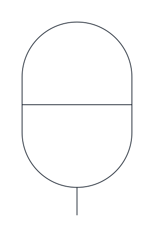
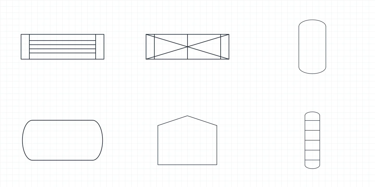
Gas-loaded accumulator
Vertical capsule divided by a separating element, storing fluid under pressure against a gas charge. Used for energy storage, pulsation damping and emergency supply.
IND_HYDRAULIC_SYMBOLS_ACCUMULATOR
-
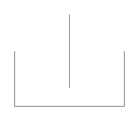
Reservoir (tank)
Open-top tank vented to atmosphere, with the line ending below the fluid level. Each return or drain line in a circuit ends at one of these symbols.
IND_HYDRAULIC_SYMBOLS_RESERVOIR
-
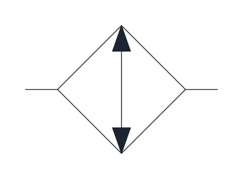
Cooler
Square on its corner with an arrow pointing outward at both ends, meaning heat leaves the fluid; coolant lines are not shown. Typically placed in the return line before the tank.
IND_HYDRAULIC_SYMBOLS_COOLER
Gauge symbols
-
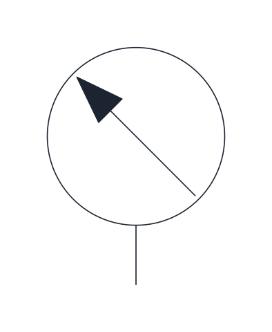
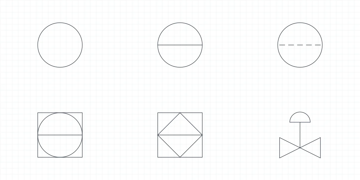
Pressure gauge
Measuring instrument circle with an oblique pointer arrow, connected to the line whose pressure it shows. Draw it at test points and after pressure control valves.
IND_HYDRAULIC_SYMBOLS_PRESSURE_GAUGE
Hydraulic line symbols
-

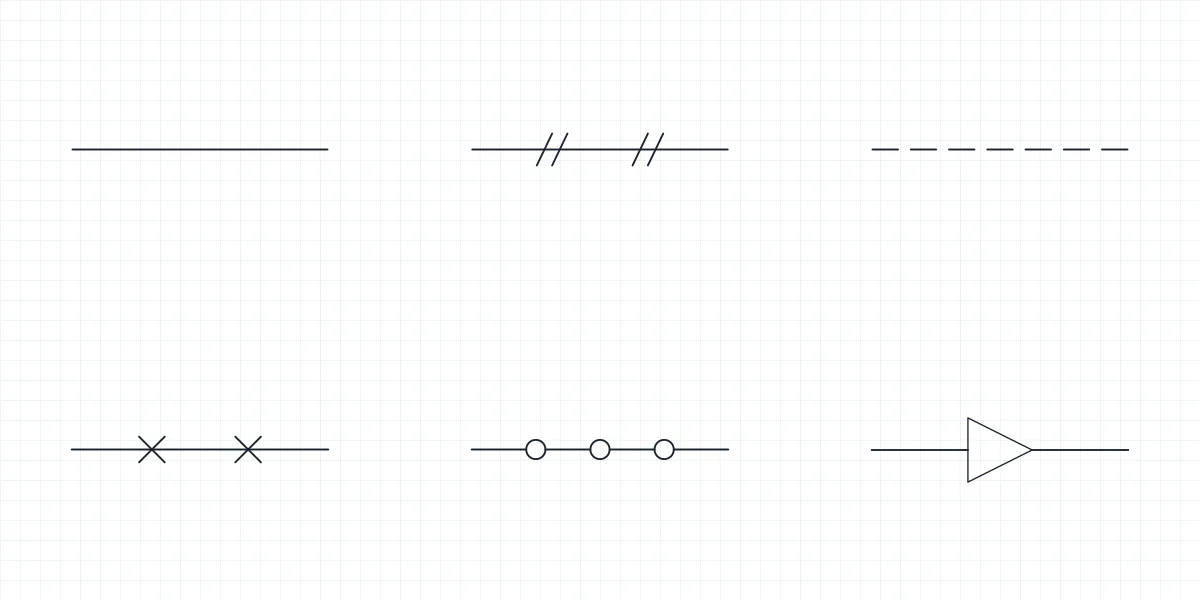
Working line
Continuous line for pressure, return and suction connections between components. It is the main flow path of the circuit.
IND_HYDRAULIC_SYMBOLS_LINE_WORKING
-

Pilot or drain line
Dashed line for pilot control signals and for drain or leakage lines. Use it to tell control connections apart from the working lines.
IND_HYDRAULIC_SYMBOLS_LINE_PILOT_DRAIN
-
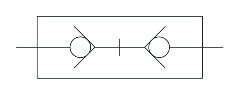
Quick coupling, connected, self-sealing
Coupled quick-release connector with a non-return valve in each half, so both sides seal when disconnected. Used on hoses to attachments and on test points that are connected and disconnected often.
IND_HYDRAULIC_SYMBOLS_QUICK_COUPLING
- Units
- Millimetres (INSUNITS 4), drawn at paper size
- Formats
- DWG 2010 · DXF R2010 · PDF
- Opens in
- AutoCAD and AutoCAD LT 2010 or later, BricsCAD, ZWCAD and DraftSight. The DXF opens in most CAD programs.
- Views
- Sheet
- License
- Free for personal and commercial projects. License
The hydraulic symbols in this library follow ISO 1219-1: pumps and motors, cylinders, directional control valves with their actuators, pressure and flow valves, filters, accumulators and the reservoir. Each symbol is its own block in the DWG and DXF, ready to wire into a circuit, and the PDF sheet gives you the full hydraulic symbols chart on one page.
How to read hydraulic schematic symbols
Hydraulic symbols describe what a component does, not what it looks like. A circle is a pump or a motor, and a small triangle on it shows the direction of energy: pointing out on a pump, pointing in on a motor. In hydraulics that triangle is filled; in pneumatics it is drawn hollow, which is the quickest way to tell the two kinds of circuit apart. An arrow drawn across a symbol means it is adjustable, as on a variable displacement pump.
Working lines are continuous. Pilot and drain lines are dashed, so you can follow the control signals separately from the power flow.
How to read directional control valve symbols
A directional control valve is drawn as a row of squares, one per switching position. Inside each square, arrows and blocked ports show how the flow passes in that position. The usual shorthand counts ports and positions: a 4/3 valve has four ports and three positions, a 4/2 valve has two positions. On hydraulic valves the ports are commonly lettered P for pressure, T for tank and A and B for the working lines.
Three-position valves differ in the centre position, and the library has the three most common ones: closed centre, tandem centre and open centre. The actuators, solenoid, spring, lever, push button and pilot, are separate blocks drawn to the same square height, so you place them at either end of any valve.
Pressure, flow and check valve symbols
Pressure control valves are drawn as a single square with an arrow and a spring. The pressure relief valve opens to tank when the inlet pressure overcomes the spring, and the pressure reducing valve holds a lower pressure at its outlet. The throttle valve narrows the line between two arcs, and the one-way flow control valve adds a check valve in parallel so the flow is restricted in one direction only. The check valve itself is a ball against a seat.
Cylinder, accumulator and filter symbols
Cylinders appear in their single-acting, double-acting and double-rod forms. The accumulator, the filter, the cooler, the pressure gauge and the reservoir complete what a typical power unit needs, and the electric motor drive goes next to the pump.
Drawing a hydraulic circuit with these blocks
All symbols are drawn at paper size on a 2.5 mm grid, with valve squares of 10 x 10 mm. The base point sits on a port: the P port of the rest position on directional valves and the cap-end port on cylinders, while the electric motor is placed by its centre. Lines drawn on the same grid connect without adjustment. Insert them from DesignCenter (ADCENTER) in AutoCAD or copy them from the DXF into any CAD program. The DWG is saved for AutoCAD 2010 and later.
ISO 1219-1 is sold by ISO and is not reproduced here. The symbols are our own drawings of its conventions; check them against the edition your project requires.
Hydraulic symbol libraries for valves and pumps
- Directional Control Valve Symbols: Hydraulic and pneumatic directional control valves, from 2/2 to 5/3, with seven actuators placed by a fixed corner.
- Hydraulic Pump Symbol: Fixed and variable displacement pumps, the hydraulic motor and the parts of a power unit, drawn to couple shaft to shaft.
- Check Valve Symbols: The check valve as drawn on a P&ID and in hydraulic and pneumatic circuits, with the valves that carry a check element.