Piping Symbols
Process and signal line types, reducer, flanged joint, spectacle blind and four in-line valves for P&IDs.
Piping symbols library
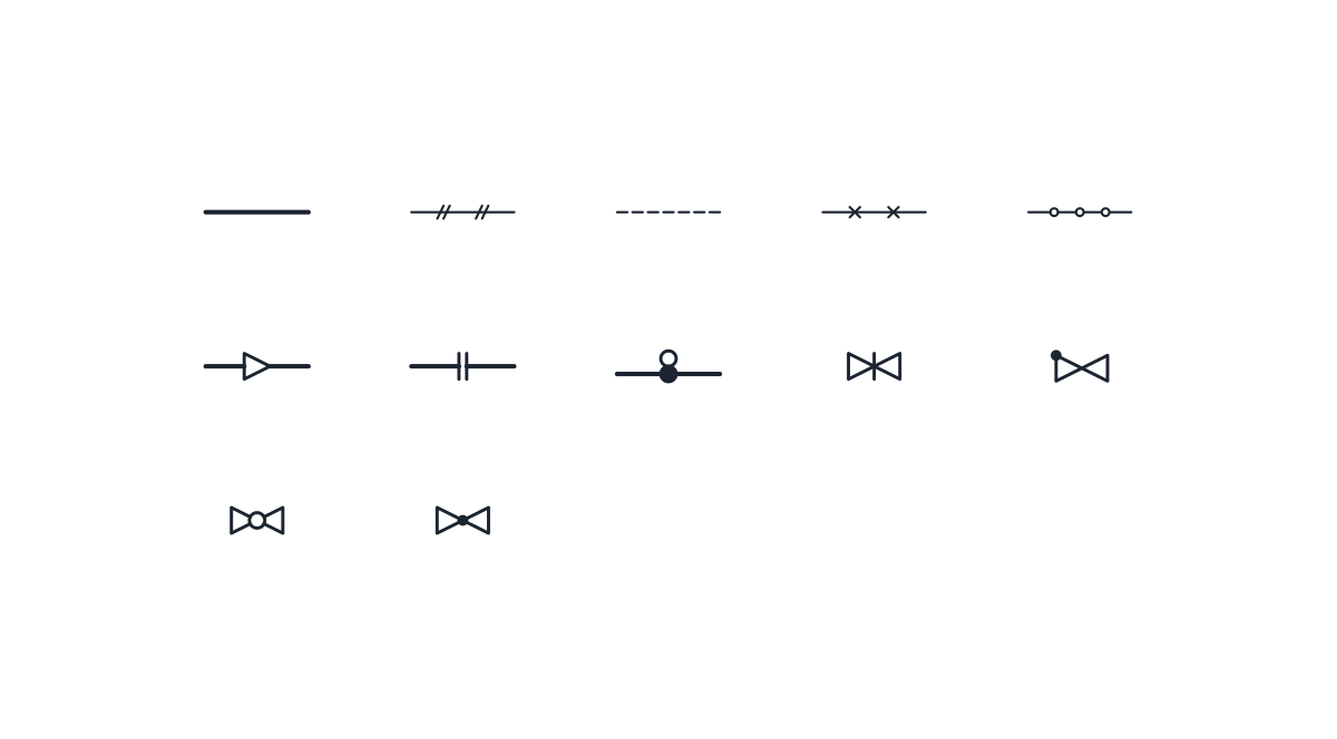
-

Process line
Heavy solid line for main process piping. Draw it on the process line layer so it stays thicker than signal and utility lines.
IND_PID_SYMBOLS_LINE_PROCESS
-
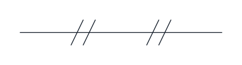
Pneumatic signal line
Thin solid line with pairs of short slashes, for an instrument air signal between a transmitter, controller and actuator.
IND_PID_SYMBOLS_LINE_PNEUMATIC_SIGNAL
-

Electrical signal line
Dashed line for an electrical or electronic signal, such as a 4-20 mA loop between a field transmitter and the control system.
IND_PID_SYMBOLS_LINE_ELECTRICAL_SIGNAL
-
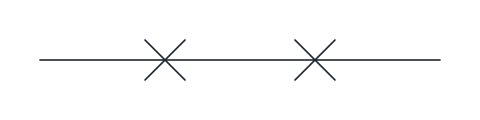
Capillary tube
Thin line with small crosses, for a filled capillary system linking a sensing bulb or remote seal to its instrument.
IND_PID_SYMBOLS_LINE_CAPILLARY
-
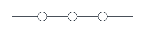
Data link
Thin line interrupted by small circles, for a communication or software link between systems, such as a fieldbus or a link between a PLC and the DCS.
IND_PID_SYMBOLS_LINE_DATA_LINK
-
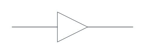
Reducer
Triangle on the line marking a change of pipe size, with the wide side towards the larger bore. Flip the block to match the direction of reduction.
IND_PID_SYMBOLS_REDUCER
-
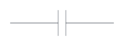
Flanged connection
Two short parallel bars across the line for a bolted flange joint. Use it where a joint must be shown, for example at equipment nozzles or removable spools.
IND_PID_SYMBOLS_FLANGE_PAIR
-

Spectacle blind
Solid disc on the line with an open ring beside it, a spectacle blind drawn in the closed position. Swap the disc and ring to show it open.
IND_PID_SYMBOLS_SPECTACLE_BLIND
-
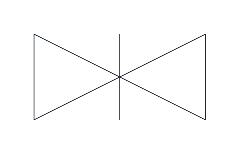
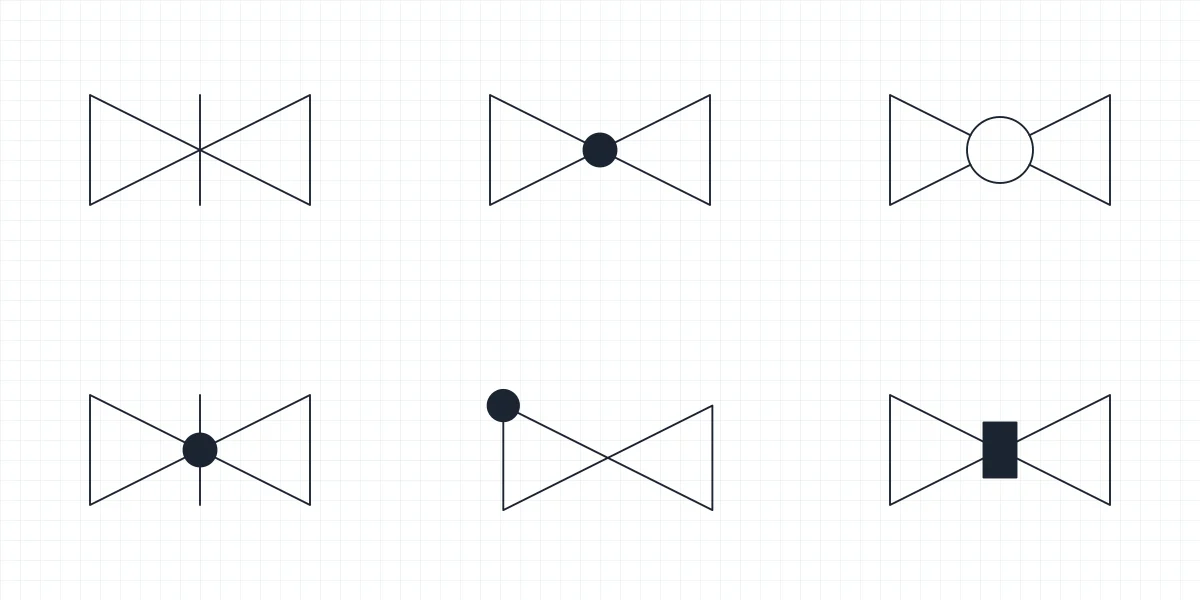
Gate valve
Two opposed triangles with a vertical bar through the centre for an on/off isolating valve whose gate slides across the flow. Use it for block valves that stay fully open or fully closed.
IND_PID_SYMBOLS_GATE_VALVE
-
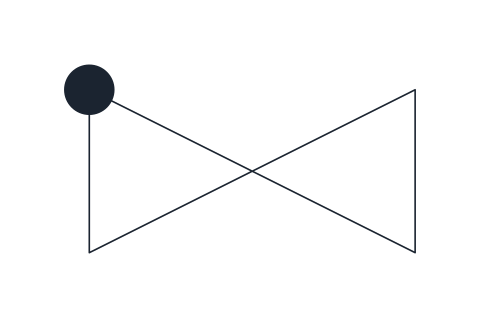
Check valve
Valve body with a solid dot on the inlet corner, the general non-return valve. Draw it with the inlet on the left so the permitted flow runs left to right.
IND_PID_SYMBOLS_CHECK_VALVE
-
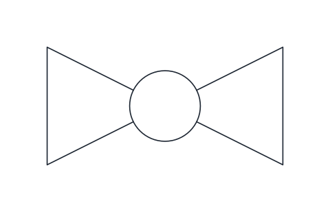
Ball valve
Valve body with an open circle at the centre for a quarter-turn valve with a bored ball. Common on utility lines and tight shut-off services.
IND_PID_SYMBOLS_BALL_VALVE
-
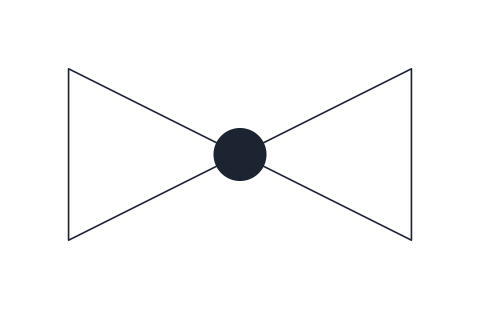
Globe valve
Valve body with a solid dot at the centre, marking a globe-pattern seat. Typical for throttling duties and bypasses where flow is adjusted by hand.
IND_PID_SYMBOLS_GLOBE_VALVE
- Units
- Millimetres (INSUNITS 4), drawn at paper size
- Formats
- DWG 2010 · DXF R2010 · PDF
- Opens in
- AutoCAD and AutoCAD LT 2010 or later, BricsCAD, ZWCAD and DraftSight. The DXF opens in most CAD programs.
- Views
- Sheet
- License
- Free for personal and commercial projects. License
This download contains 12 piping symbols for P&IDs as named blocks in DWG and DXF, with a PDF legend: five line types (process line, pneumatic signal, electrical signal, capillary tube and data link), three fittings (reducer, flanged connection and spectacle blind) and four common in-line valves, gate, check, ball and globe. Names match the full library, such as IND_PID_SYMBOLS_SPECTACLE_BLIND, so the same block comes out of either file.
Piping line symbols and line types
Every line sample is 20 mm long, with its base point on the left end. The process line is a heavy solid line on layer D-PID-LINE, which plots at 0.35 mm, while signal lines plot at 0.18 mm. That difference in weight is what lets the reader follow the process at a glance. The pneumatic signal is a thin line with pairs of short slashes, the capillary tube has small crosses and the data link is broken by small circles. The electrical signal is a dashed line on layer D-PID-SIGN with the DASHED_S linetype, so its look depends on LTSCALE. Copy any sample and use MATCHPROP to pass its layer to lines you have already drawn.
Reducer symbol
The reducer is a triangle on the line with the wide side towards the larger bore, the form used in ISO drawings. Mirror the block to match the direction of the reduction. Many American legends draw it as a trapezoid instead, so if a client legend shows that form, follow it. Write both sizes next to the symbol, as the triangle only says that the size changes.
Flange and spectacle blind symbols
The flanged connection is two short parallel bars across the line for a bolted joint. Show it where the joint matters, for example at equipment nozzles, removable spools or the break between two piping classes. The spectacle blind is a solid disc in the line with an open ring beside it, which is the blind in the closed position. To show it open, swap the two so the ring sits in the line. Fittings are drawn on layer D-PID-VALV, and the line pieces on either side stay on D-PID-LINE.
Valve symbols on a piping line
The gate, check, ball and globe valves are 10 mm long and 5 mm high, with the base point on the left connection and the right one 10 mm along, so they land on a line drawn on the 2.5 mm grid. The gate valve has a bar, the globe a solid dot, the ball an open circle and the check valve a dot on its inlet corner. The other eleven valve types, actuated valves among them, are on the valve symbols page, the bubbles that signal lines connect to are on the instrumentation symbols page, and everything is in the P&ID symbols library.
Piping and fitting symbols are drawn after ISO 10628-2 and the signal lines after ISA-5.1. Each standard is sold by the body that publishes it, and neither is reproduced here.