
CAD libraries
Valve CAD Blocks
Industrial valves drawn as plan and front elevation in millimetres, with flanges, handwheels and actuators. Each size is its own block, and every block downloads in DWG and DXF.
-
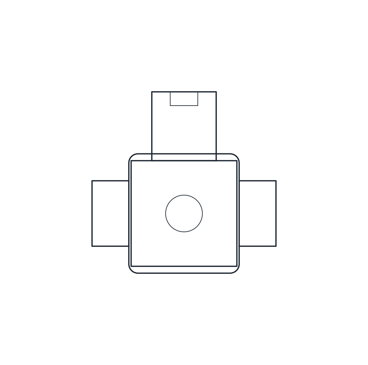 Valves Solenoid Valve CAD Block
-
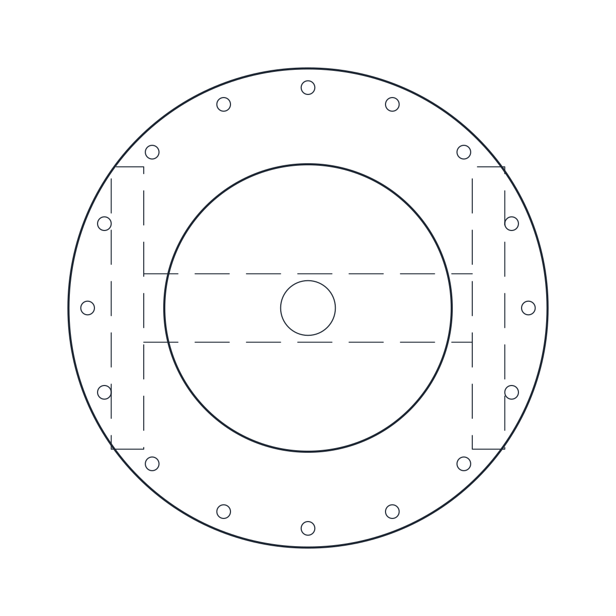 Valves Control Valve CAD Block
-
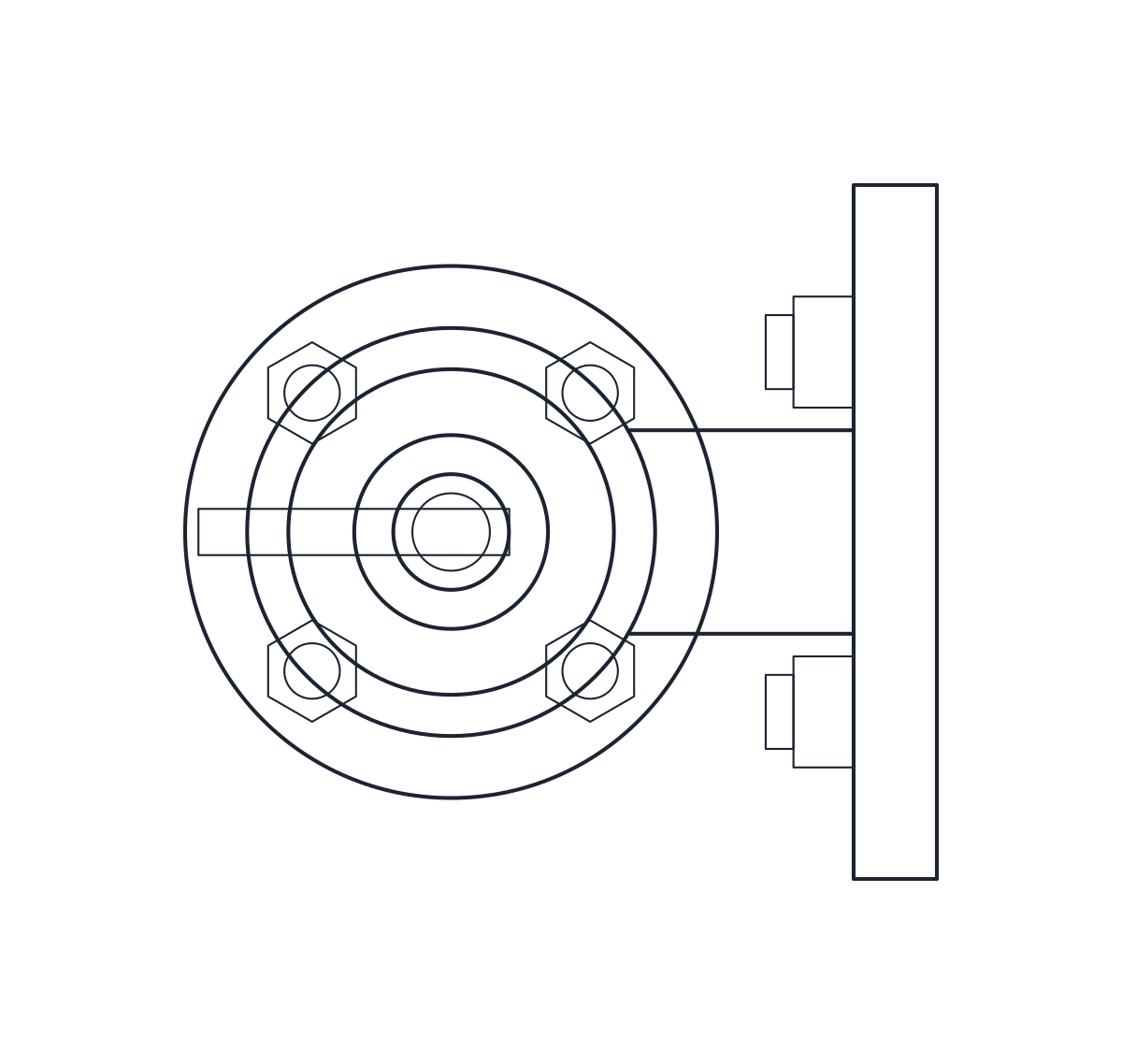 Valves Safety Valve CAD Block
-
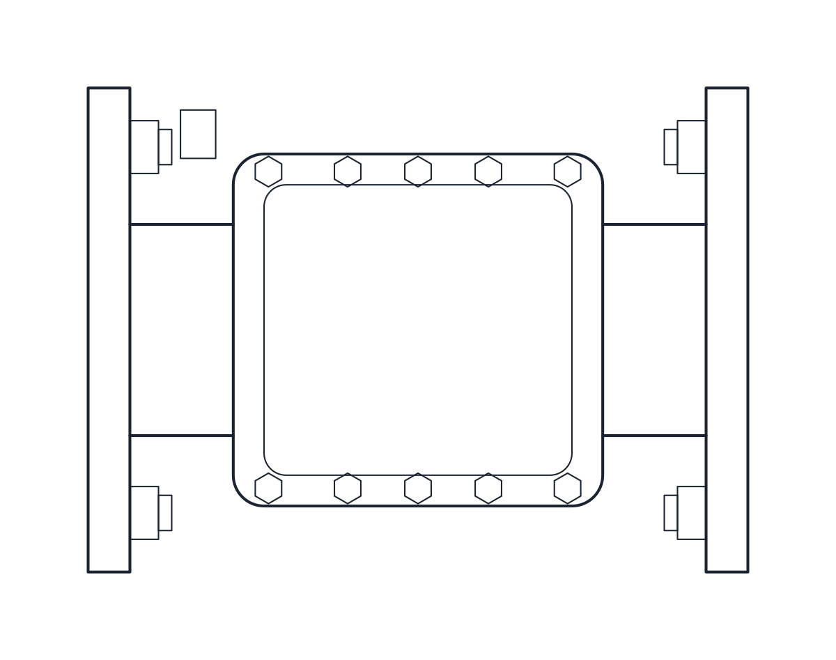 Valves Check Valve CAD Block
-
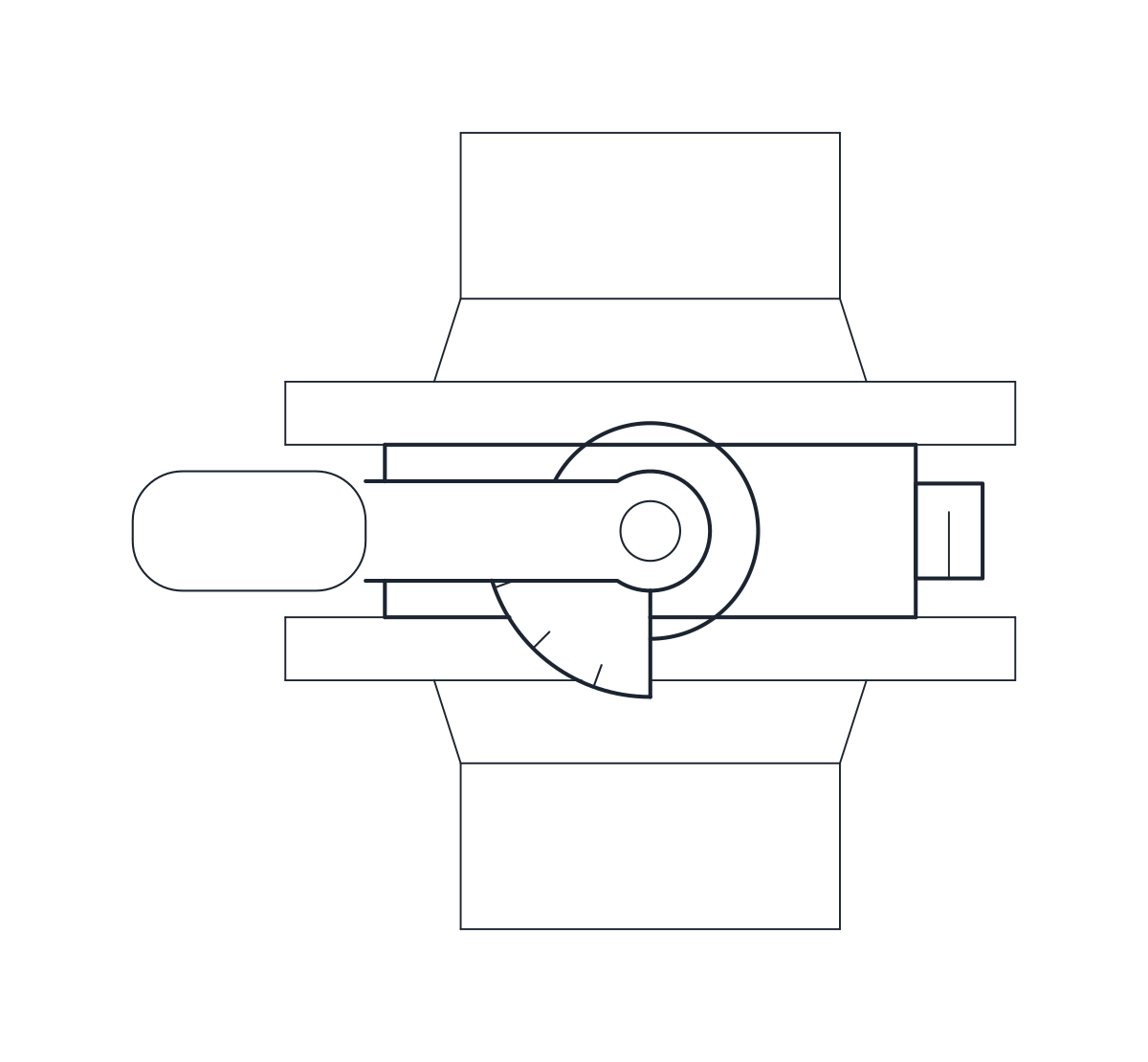 Valves Butterfly Valve CAD Block
-
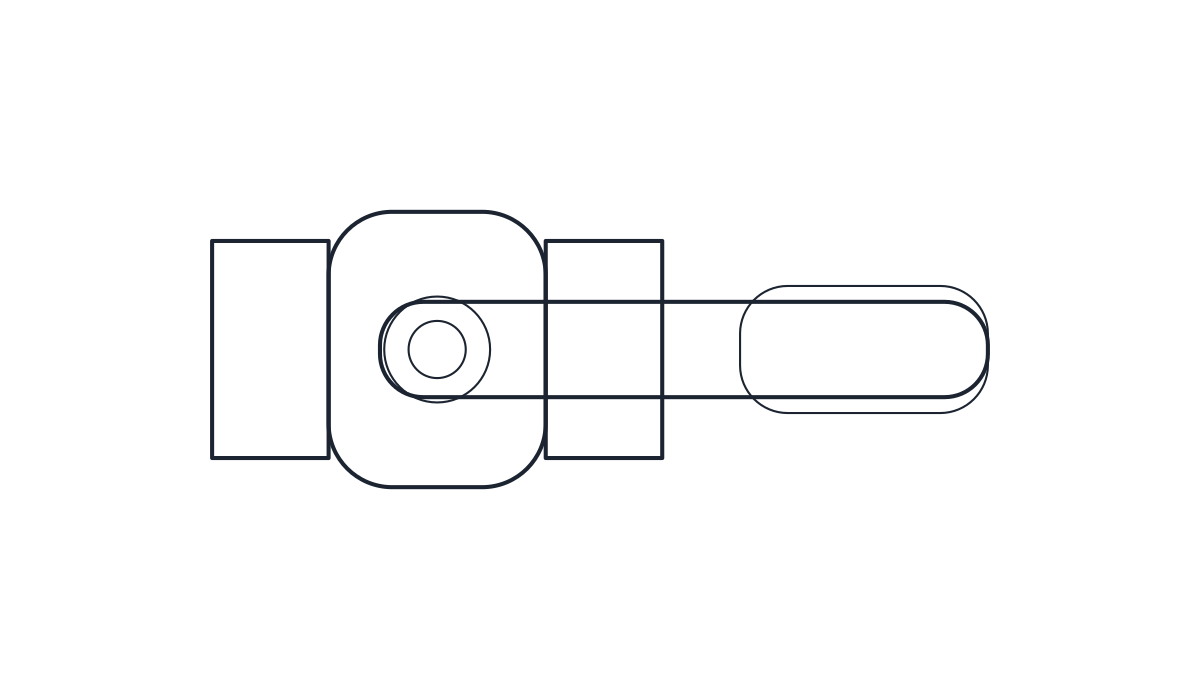 Valves Ball Valve CAD Block
-
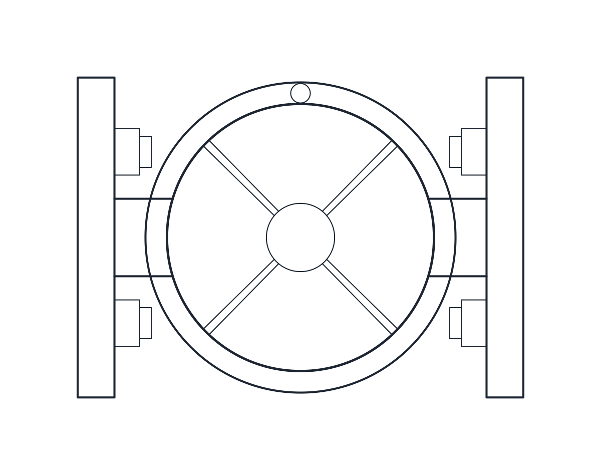 Valves Globe Valve CAD Block
-
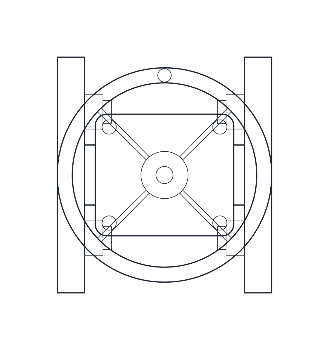 Valves Gate Valve CAD Block
Valve CAD blocks in plan and elevation
Each valve here is drawn twice: a plan view from above and a front elevation with the pipe axis horizontal. Flanged valves show their flanges and nuts, and gate and globe valves show the handwheel and the rising stem at the height of a typical catalogue valve, so you can check clearances in a piping layout.
Sizes and what to check before you use them
Every size is its own block. The dimensions come from public datasheets of typical catalogue valves and are given on each page. Face to face lengths and handwheel heights differ between makers, so compare them with the valve you specify before you fix a layout.
Valve blocks and valve symbols
For process diagrams you need the symbol, not the drawing. The valve symbols set has the P&ID forms of the same valve types as named blocks.