Solenoid Valve CAD Block
Threaded brass solenoid valves DN15 and DN25, 80 and 109 mm long and 99 and 113 mm high.
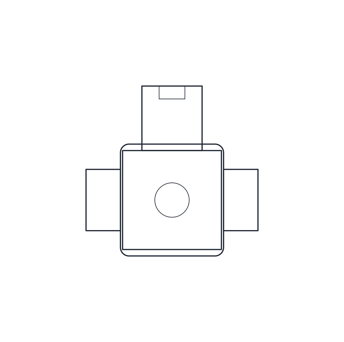
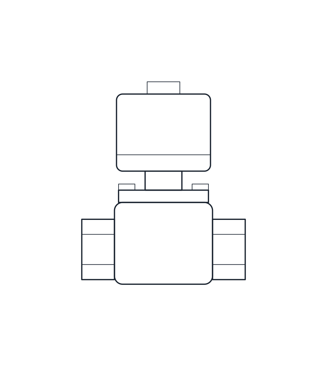
Solenoid valve DN15 (G 1/2), servo-operated, brass
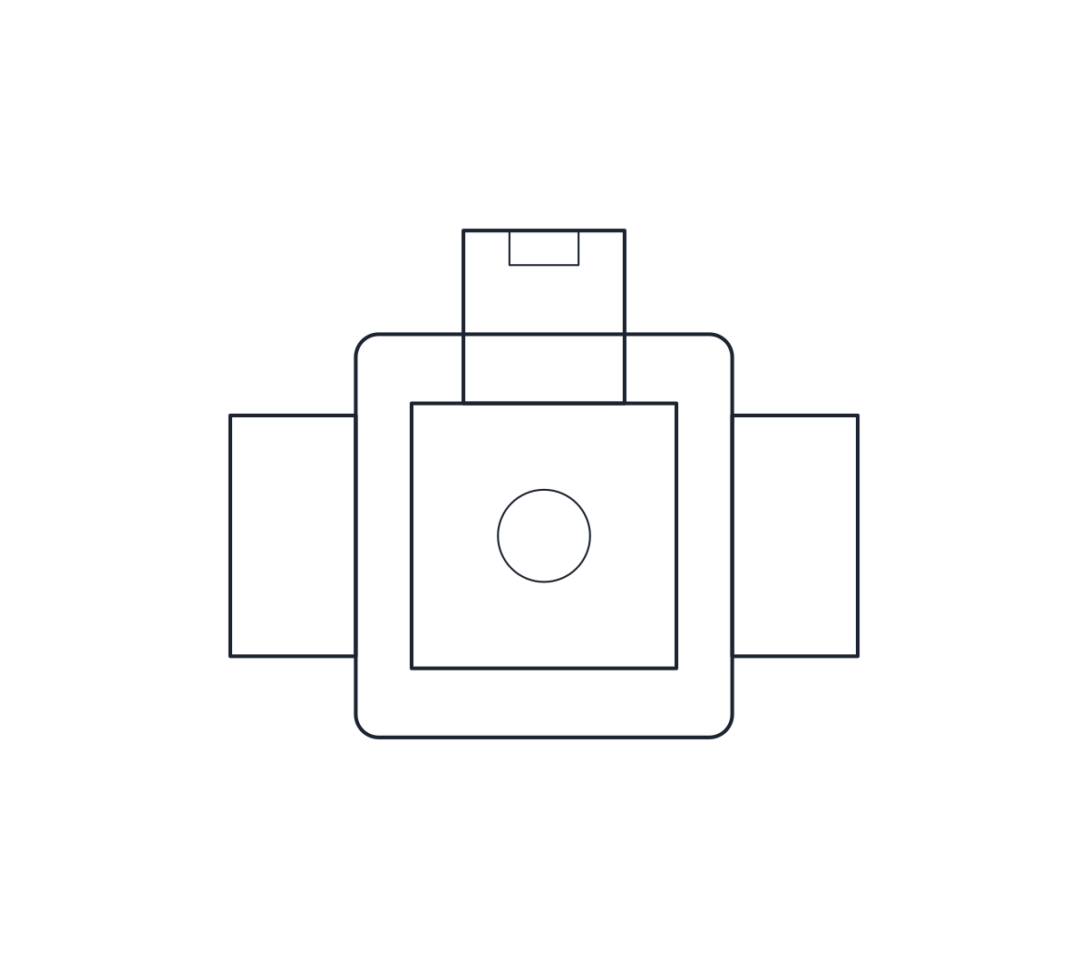
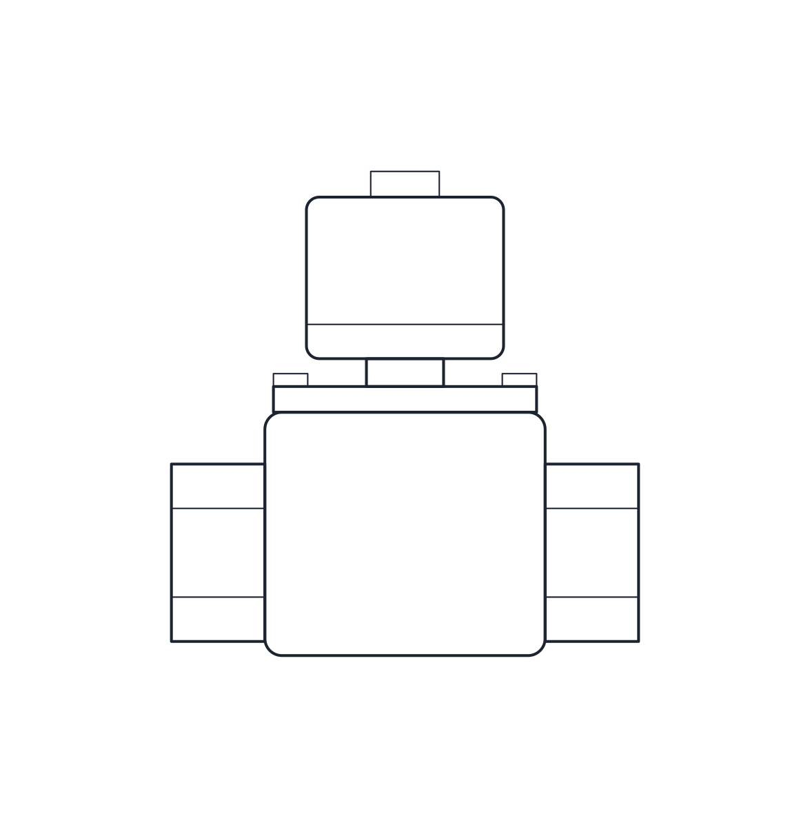
Solenoid valve DN25 (G 1), servo-operated, brass
- Units
- Millimetres (INSUNITS 4), drawn at paper size
- Formats
- DWG 2010 · DXF R2010
- Opens in
- AutoCAD and AutoCAD LT 2010 or later, BricsCAD, ZWCAD and DraftSight. The DXF opens in most CAD programs.
- Views
- Plan view + Front elevation
- License
- Free for personal and commercial projects. License
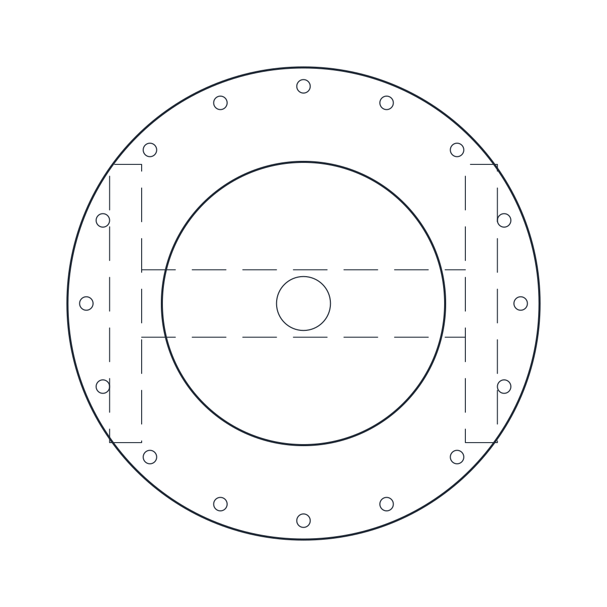
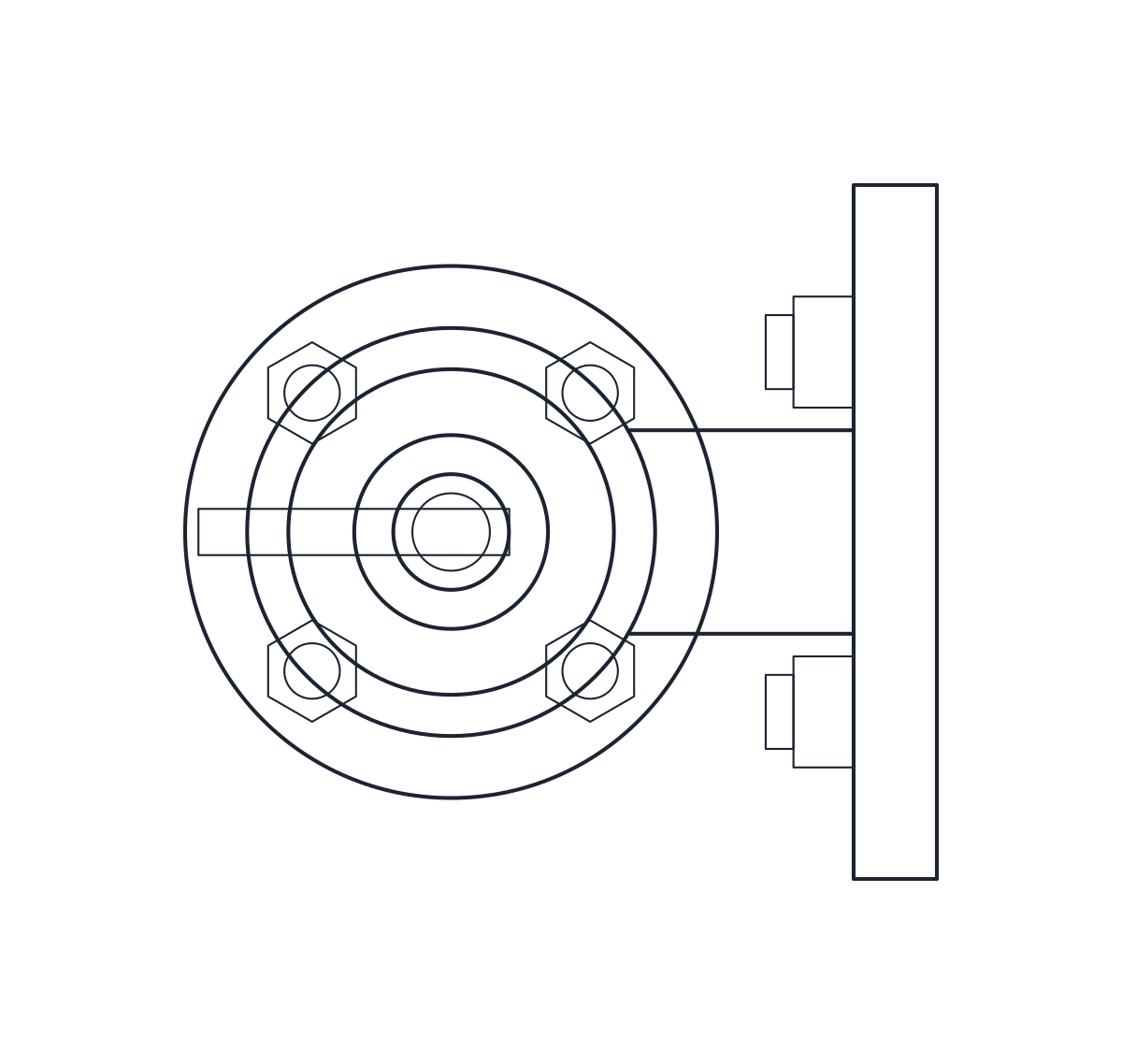
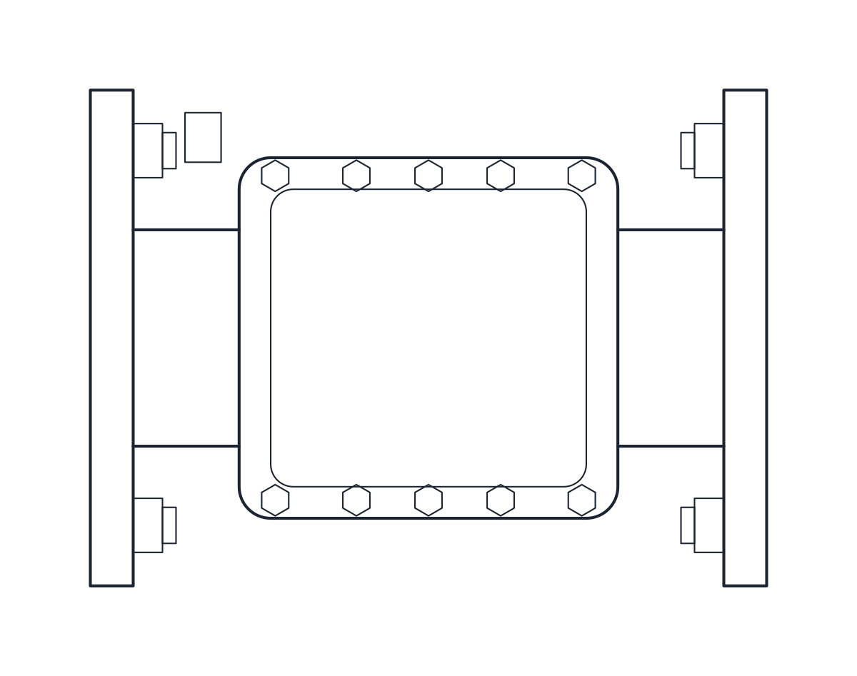
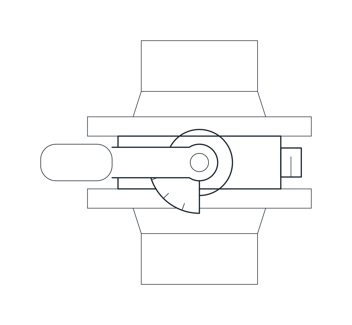
This download holds two servo-operated brass solenoid valves with threaded ends: DN15 with G 1/2 ports and DN25 with G 1 ports. Both have a coil with a DIN plug on top. Each size comes as a plan block and an elevation block in millimetres at full size, in a DWG for AutoCAD 2010 and later and in a DXF.
Solenoid valve DWG dimensions
The measurements come from a typical catalogue valve, so check them against the datasheet of the valve and coil you choose.
- DN15: 80 mm long, 52 mm body width, 99 mm high, pipe axis 15 mm above the base.
- DN25: 109 mm long, 70 mm body width, 113 mm high, pipe axis 22 mm above the base.
The coil is 46 mm wide on both sizes. The coil height, the split between body and coil and the position of the plug are representative. The plug is drawn pointing backwards, which is why the plans are 79 and 88 mm deep. Coils from different ranges vary in size, so treat those parts as indicative.
Solenoid valve drawing in plan and elevation
The elevation shows the body with its two threaded ends, the armature tube and the coil with the plug. The plan shows the square coil over the body and the plug behind it. The outlines are on layer M-VALV and the smaller parts on M-VALV-DETL. These blocks are small, so at 1:20 or smaller you may prefer the P&ID mark, a square with a diagonal on the valve stem, shown with the valve symbols.
Using the solenoid valve block on a water or air line
Insert the block on the pipe axis, 15 or 22 mm above the base, with the coil upright. A servo-operated valve needs a minimum pressure difference to open, so it suits lines with steady pressure. Leave space in front of the plug for the cable gland and for the coil to slide off for replacement. Where the line needs a manual isolating valve next to it, the ball valve block has a DN25 threaded size.