Safety Valve CAD Block
Angle safety valves DN25 x DN40 and DN50 x DN80, 304 and 512 mm from inlet face to top.
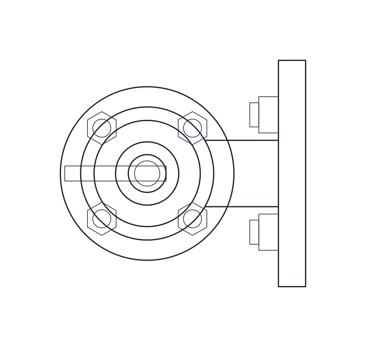
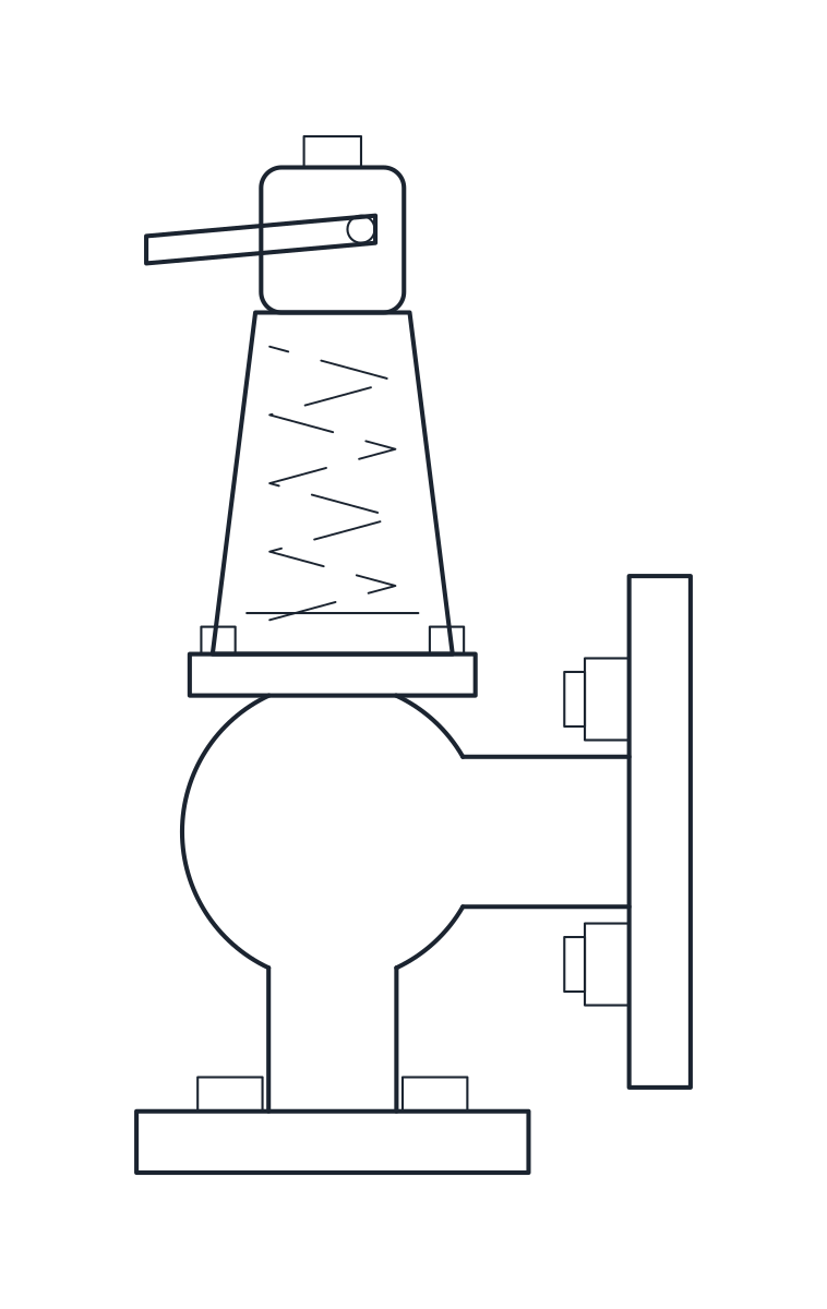
Safety valve DN25 x DN40, angle pattern, flanged
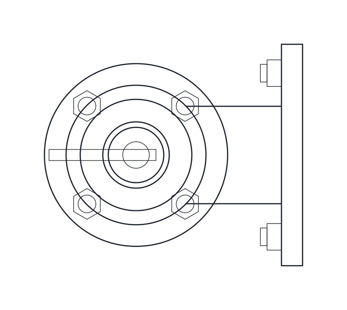
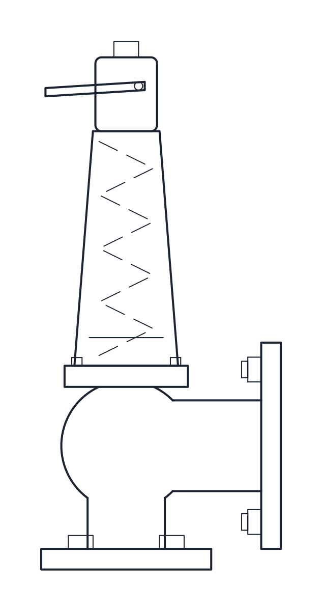
Safety valve DN50 x DN80, angle pattern, flanged
- Units
- Millimetres (INSUNITS 4), drawn at paper size
- Formats
- DWG 2010 · DXF R2010
- Opens in
- AutoCAD and AutoCAD LT 2010 or later, BricsCAD, ZWCAD and DraftSight. The DXF opens in most CAD programs.
- Views
- Plan view + Front elevation
- License
- Free for personal and commercial projects. License
This download holds two spring-loaded full-lift safety valves of angle pattern: DN25 inlet with DN40 outlet, and DN50 inlet with DN80 outlet. Both have the inlet flange underneath, a side outlet flange and a cap with a lifting lever. Each comes as a plan block and an elevation block in millimetres at full size, in a DWG for AutoCAD 2010 and later and in a DXF.
Safety valve DWG dimensions
The measurements come from a typical catalogue valve, so check them against the datasheet of the valve you select.
- DN25 x DN40: 304 mm from the inlet face to the top, 105 mm from the inlet axis to the outlet face, 100 mm from the inlet face to the outlet axis.
- DN50 x DN80: 512 mm from the inlet face to the top, 150 mm from the inlet axis to the outlet face, 120 mm from the inlet face to the outlet axis.
The inlet flanges are drawn PN40 (115 mm on DN25, 165 mm on DN50) and the outlets PN16 (150 mm on DN40, 200 mm on DN80), all to EN 1092. The datasheet table does not name the two offset columns. The block reads them in the usual way for this valve type, so confirm both offsets before you route the discharge pipe. Bonnet, cap and lever are representative shapes.
Safety valve drawing in plan and elevation
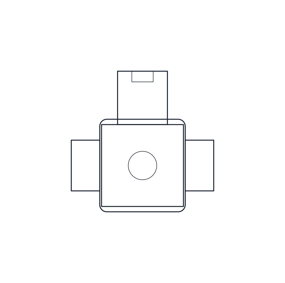
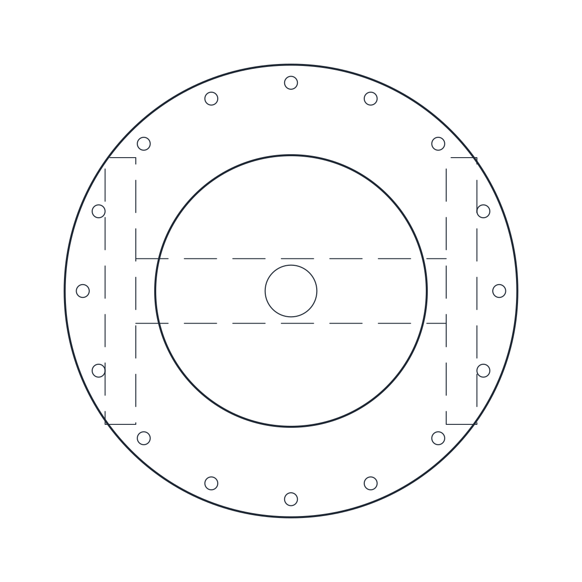
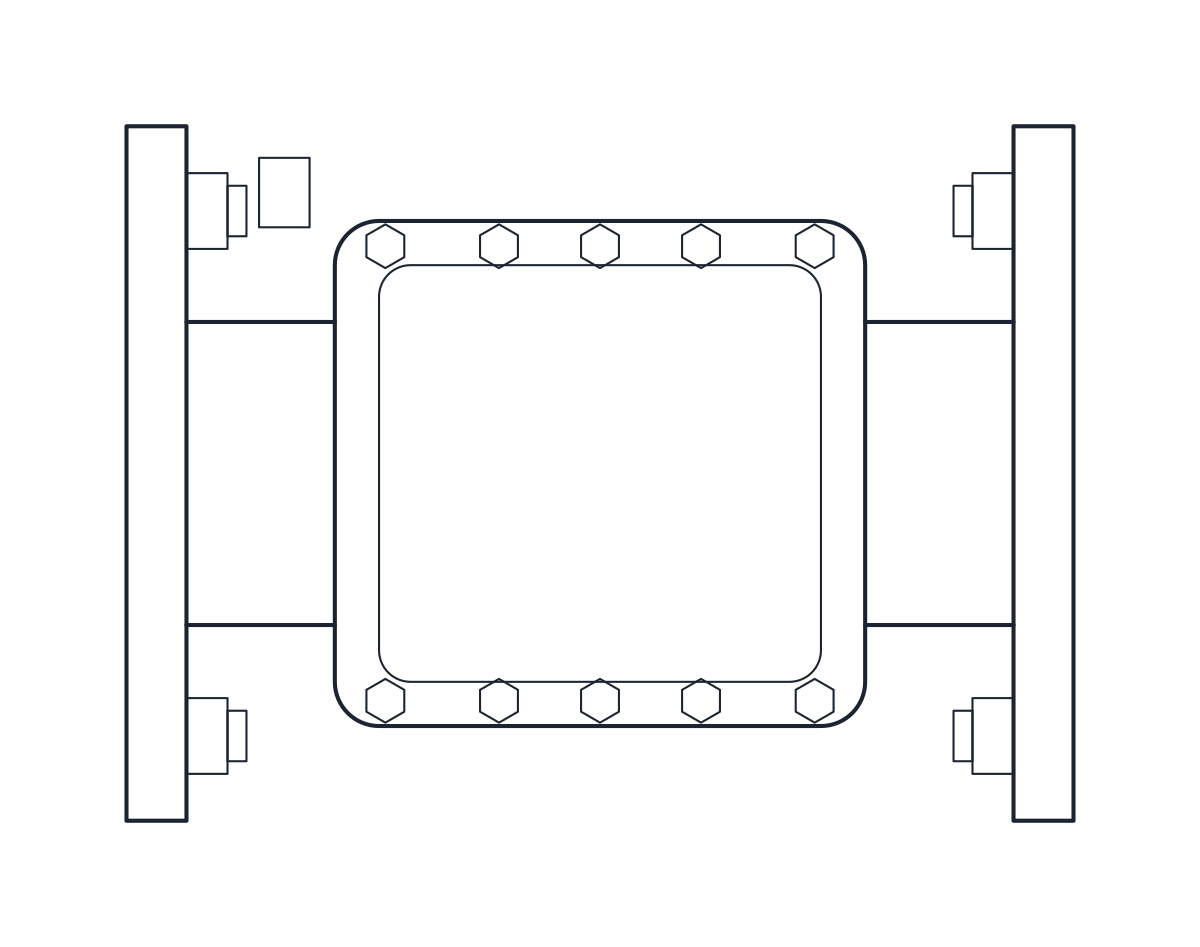
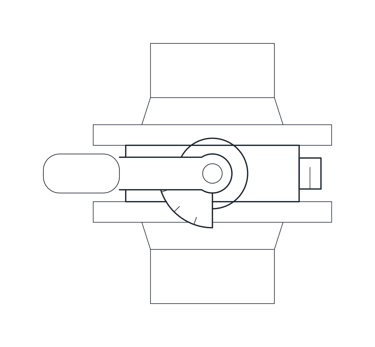
The elevation starts at the inlet face and shows the body, the outlet flange to the side, the bonnet with the spring as a hidden zigzag on layer A-HIDN, and the cap with its lever on top. The blocks are 162.5 x 150 x 304 mm and 232.5 x 200 x 512 mm. In plan the round inlet flange and the bonnet sit at one end and the outlet flange at the other.
Placing the safety valve block on a vessel or line
Insert the block with the inlet face on the nozzle of the vessel or the branch of the line, and keep the spring vertical. Rotate the block in plan to point the outlet at the discharge route. On a P&ID the safety relief valve is drawn with its spring among the valve symbols. For the valve that stops reverse flow on the same system, see the check valve block.