Butterfly Valve CAD Block
Wafer butterfly valves, DN100 with lever and DN200 with gearbox, 52 and 60 mm thick and 364 and 569 mm high.
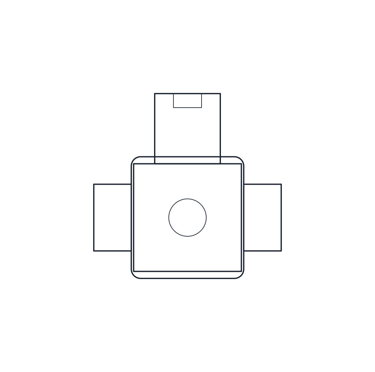
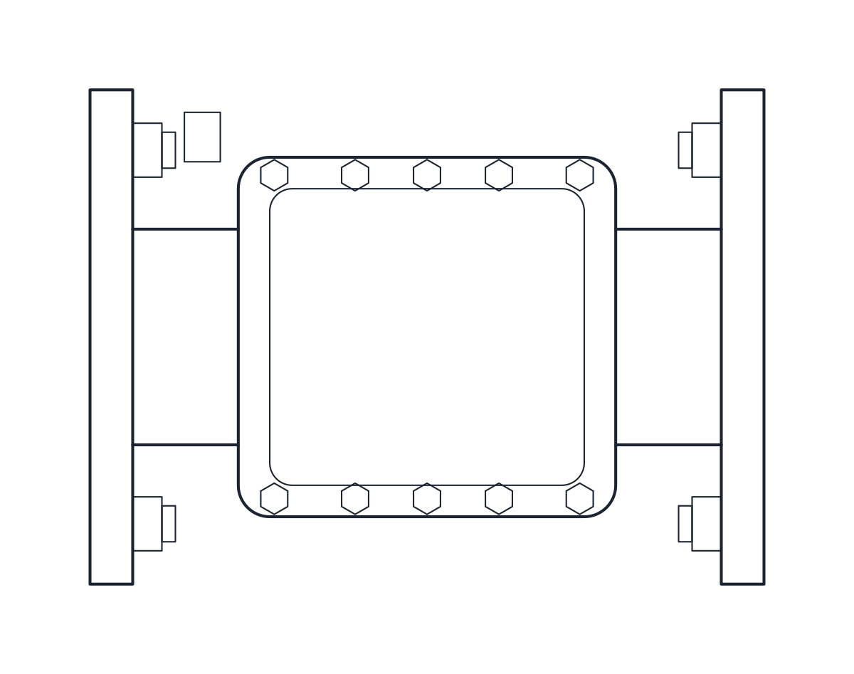
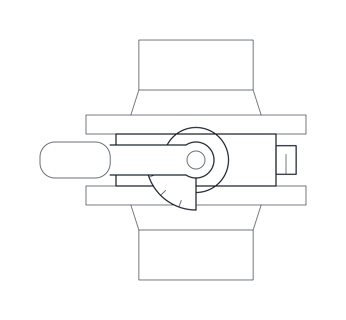
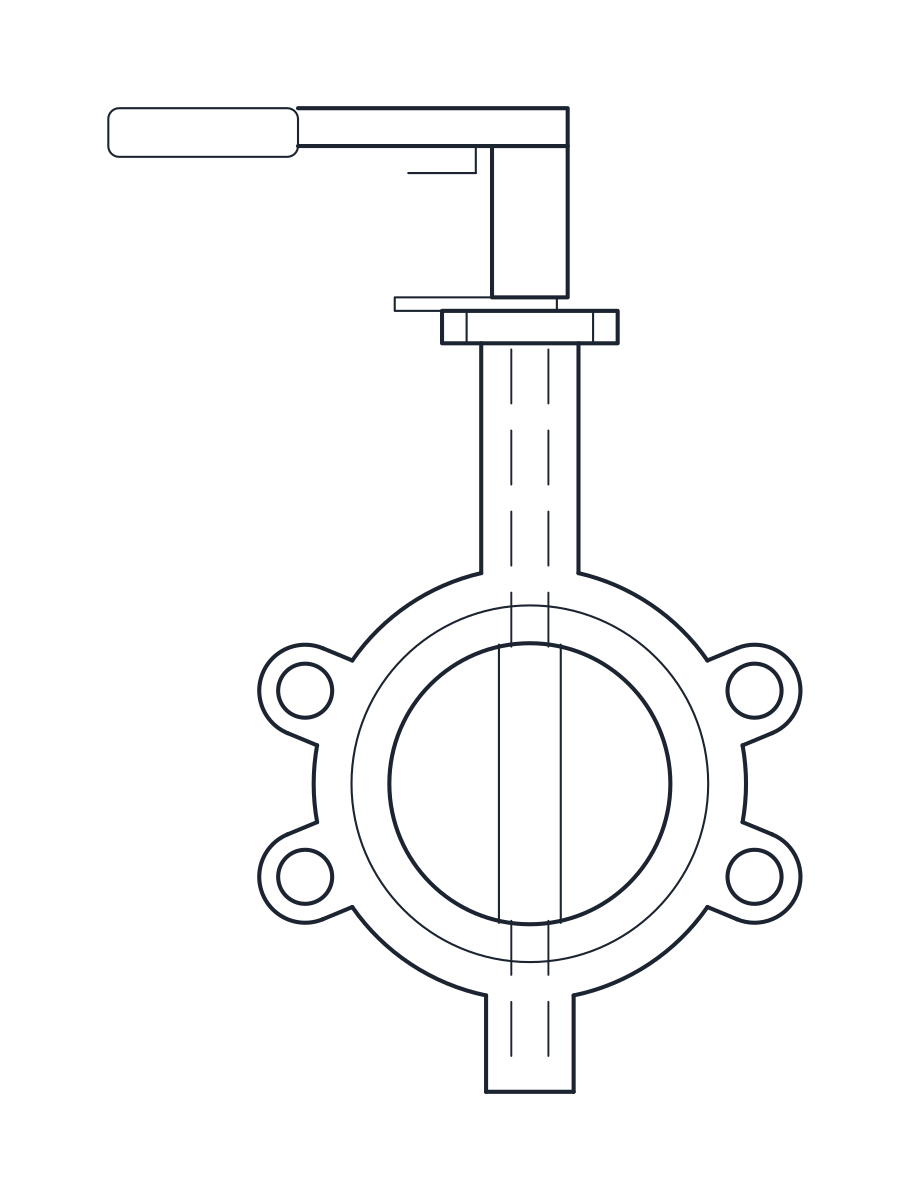
Butterfly valve DN100, wafer, lever
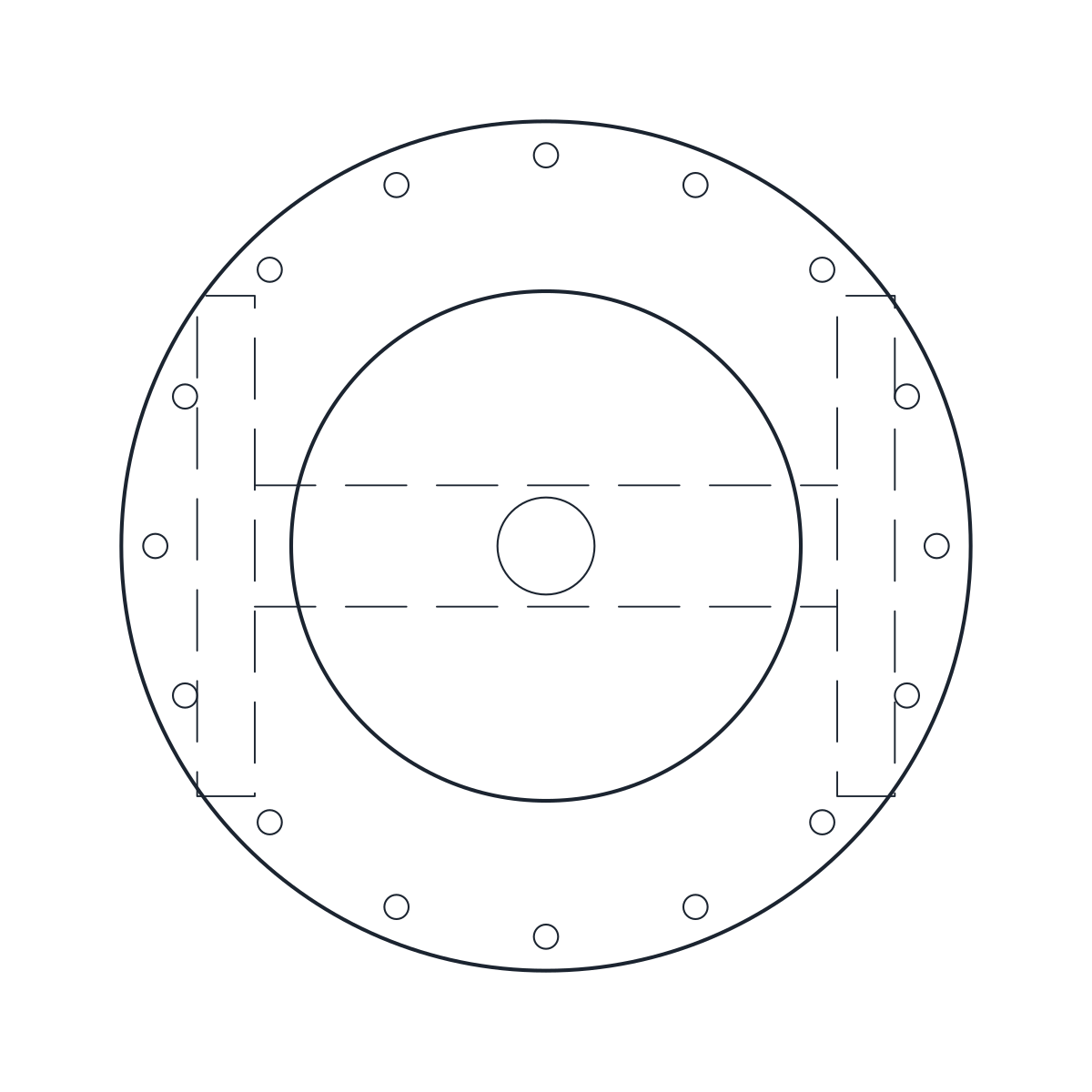
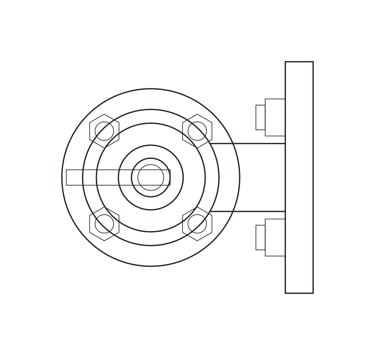
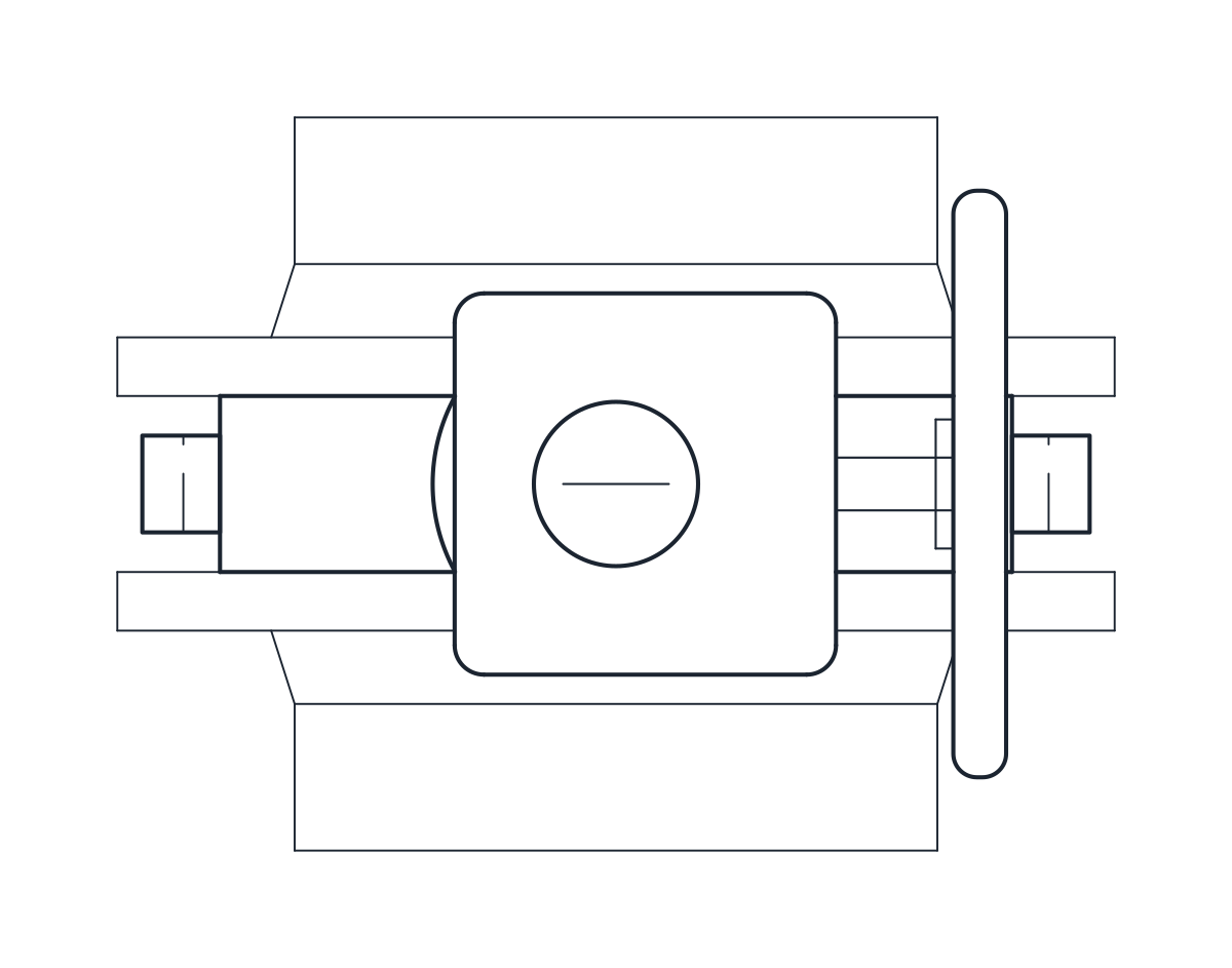
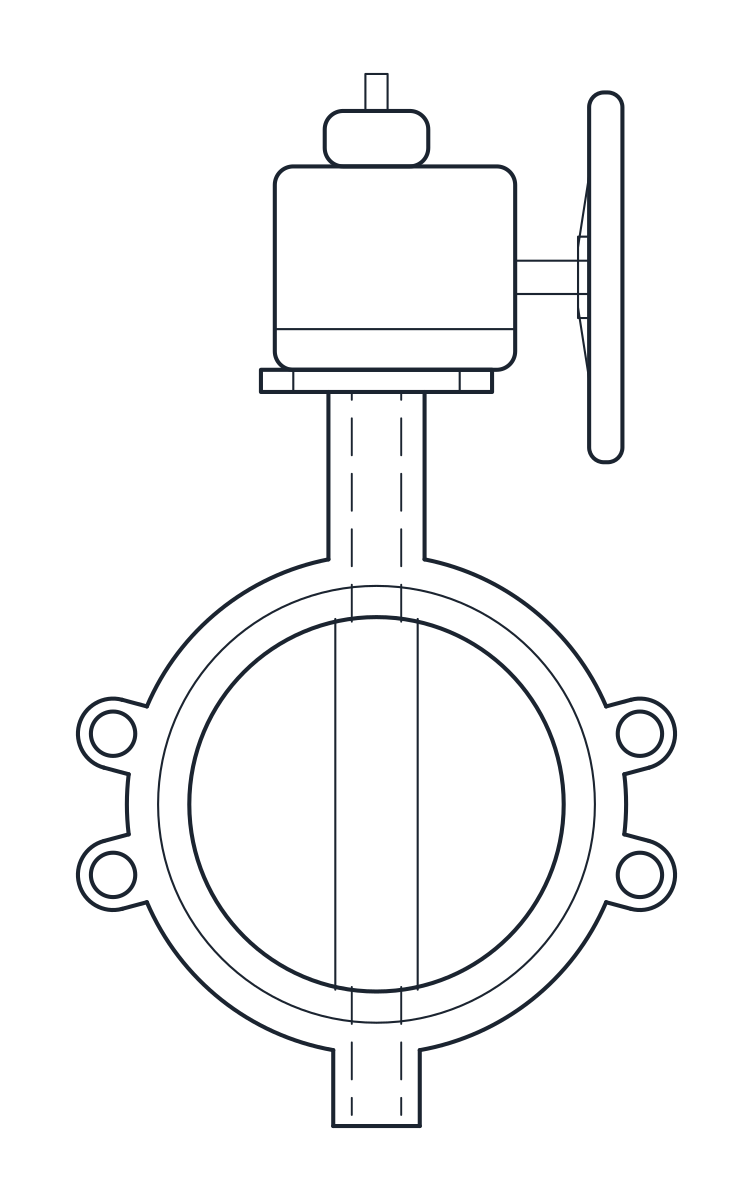
Butterfly valve DN200, wafer, gearbox and handwheel
- Units
- Millimetres (INSUNITS 4), drawn at paper size
- Formats
- DWG 2010 · DXF R2010
- Opens in
- AutoCAD and AutoCAD LT 2010 or later, BricsCAD, ZWCAD and DraftSight. The DXF opens in most CAD programs.
- Views
- Plan view + Front elevation
- License
- Free for personal and commercial projects. License
This download holds two wafer butterfly valves: a DN100 valve with a lever and a DN200 valve with a worm gearbox and handwheel. Each comes as a plan block and an elevation block in millimetres at full size, in a DWG for AutoCAD 2010 and later and in a DXF.
Butterfly valve DWG dimensions
The wafer bodies follow EN 558 series 20. The other measurements come from typical catalogue valves, so check them against the datasheet of the valve you choose.
- DN100: 52 mm thick, 175 mm from the pipe axis to the top of the ISO 5211 F05 mounting pad, 114 mm from the axis to the bottom of the body, lever 170 mm long and 75 mm above the pad.
- DN200: 60 mm thick, 235 mm from the axis to the F10 pad, 174 mm from the axis to the bottom.
The outside diameter of the body and the size of the pads are drawn to representative proportions. On DN200 the gearbox and its 200 mm handwheel are also representative, because the datasheet gives only the F10 pad. The DN100 lever length was read from the datasheet and looks short for the size, so check it before you use it for clearances.
Butterfly valve drawing in plan and elevation
The elevation is drawn side on to the pipe, so it shows the thin wafer body standing up, 52 or 60 mm wide, with the neck, the pad and the operator on top. The disc and its shaft are hidden lines on layer A-HIDN. The blocks are 185 x 160 x 364 mm for DN100 and 178 x 270 x 569 mm for DN200. In plan the lever or the gearbox and handwheel stick out to one side of the body.
Using the butterfly valve block between flanges
A wafer valve has no flanges of its own. It is clamped between the two pipe flanges with long bolts, so draw the pipe flanges on each side and add their thickness to the 52 or 60 mm of the body. Leave room for the lever to turn through 90 degrees, or for a hand on the gearbox wheel. For a lever valve with flanged ends, see the ball valve block. The P&ID form is with the other valve symbols.