Check Valve CAD Block
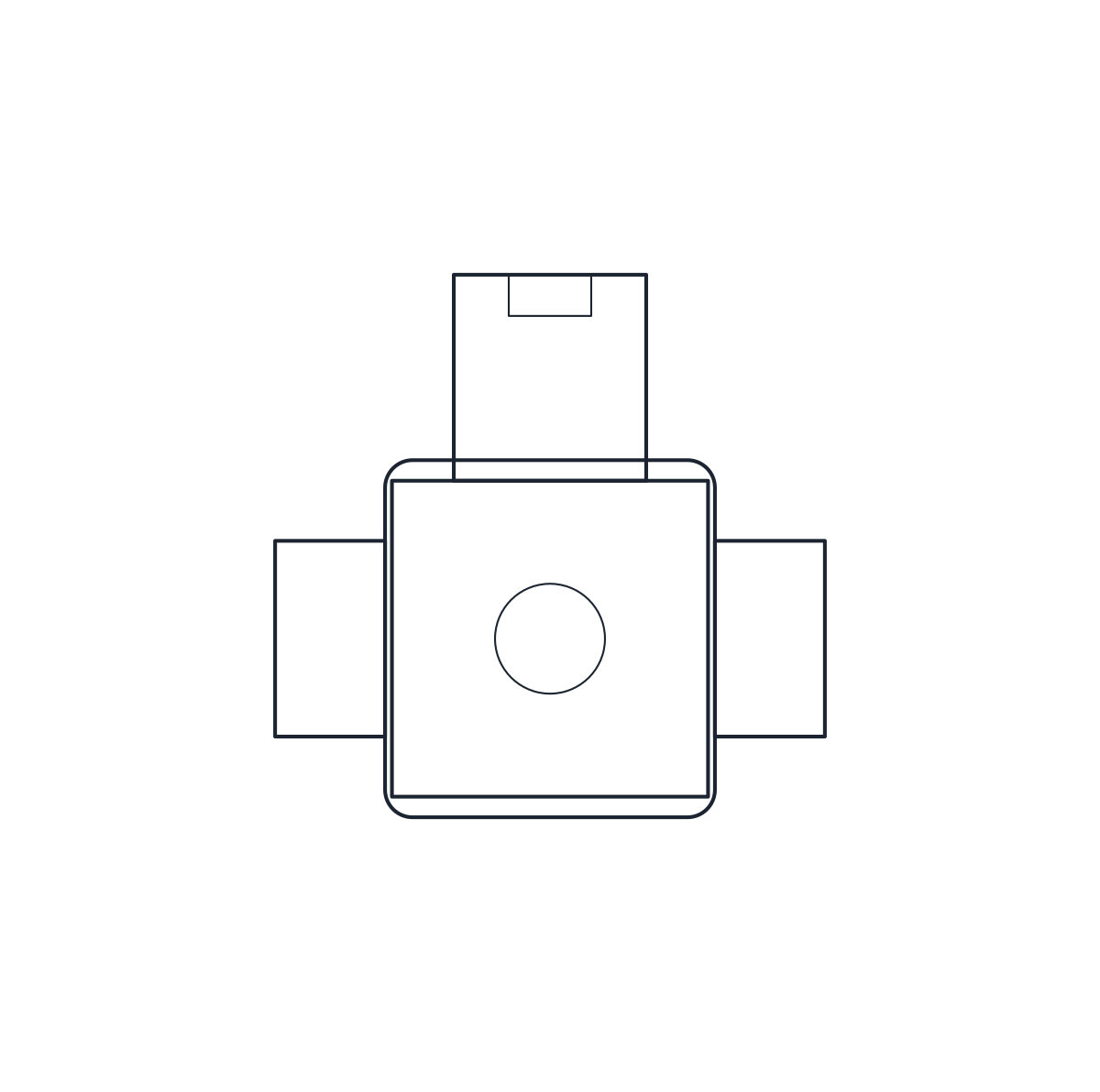
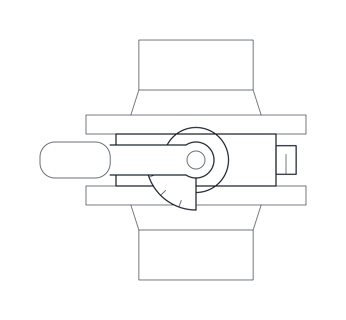
Two DN100 check valves: a flanged swing check, 300 mm face to face, and a wafer dual plate, 64 mm thick.
Swing check valve DN100 PN16, flanged
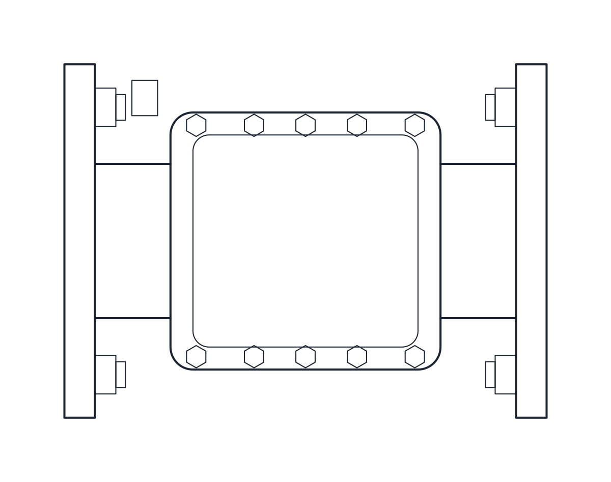
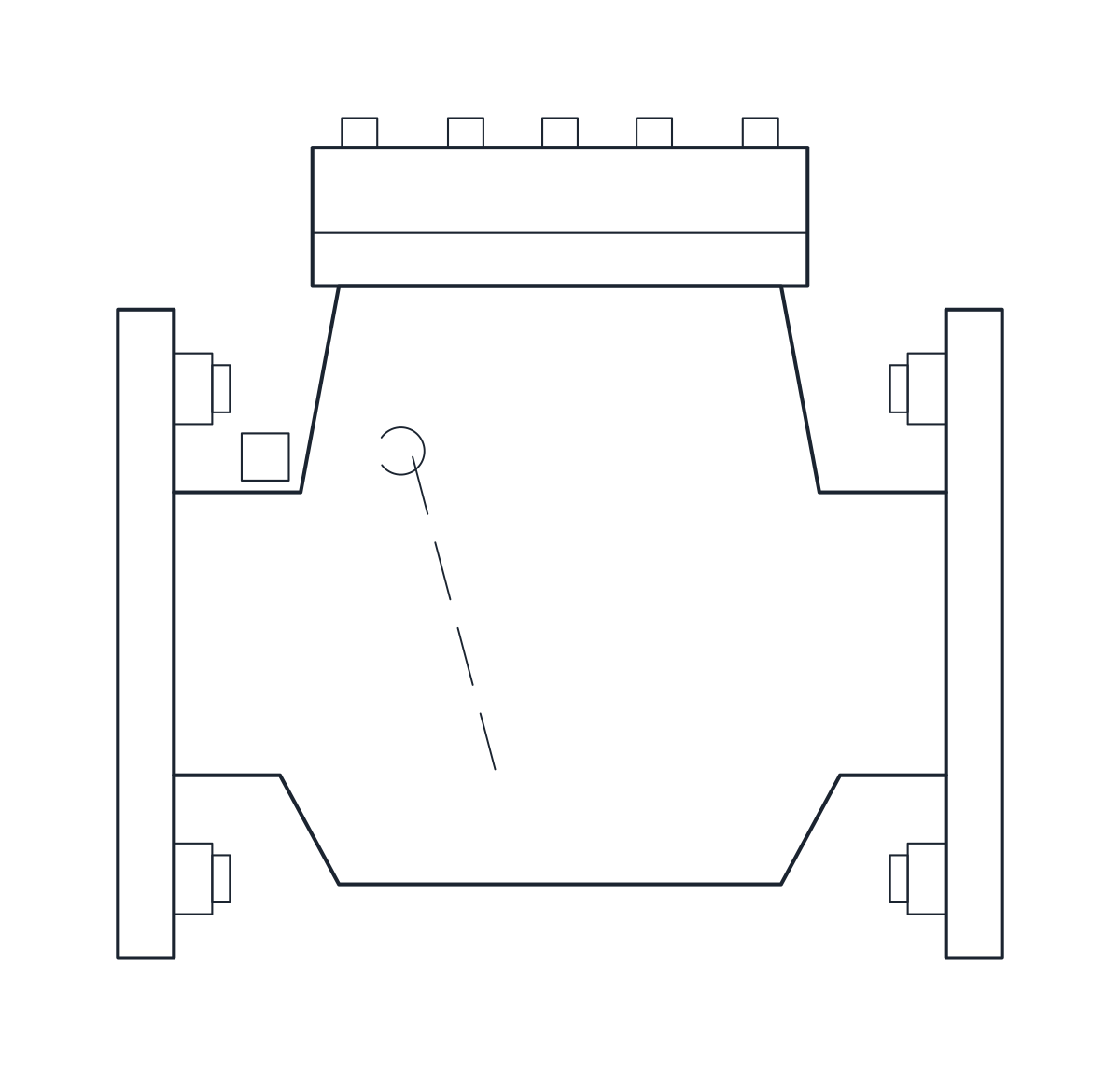
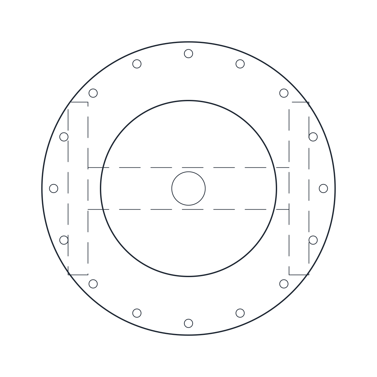
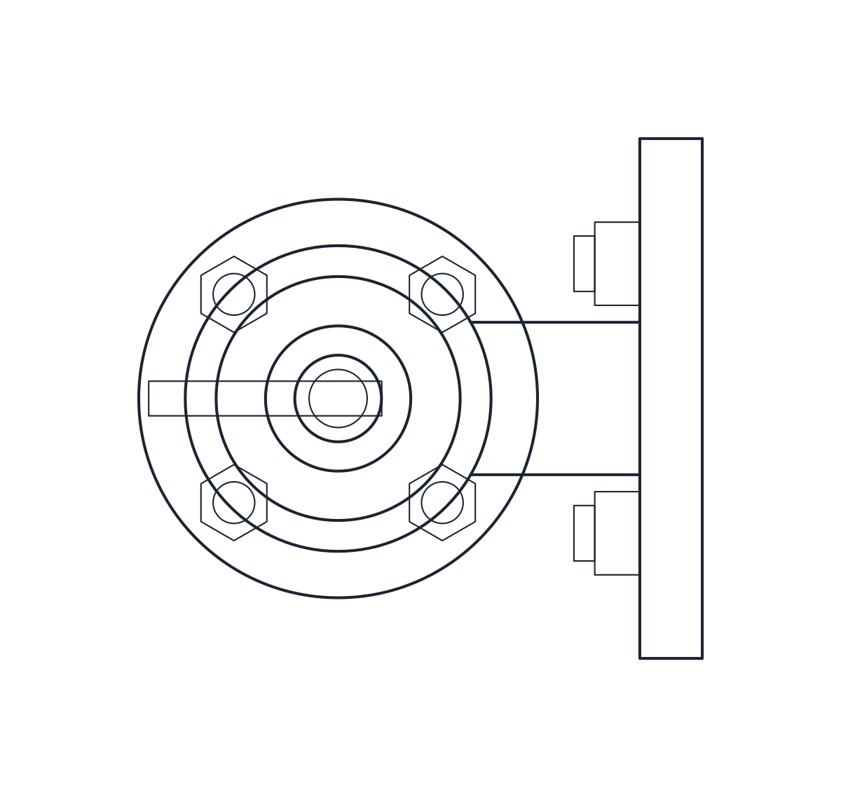
Dual plate check valve DN100, wafer
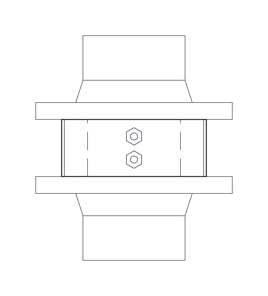
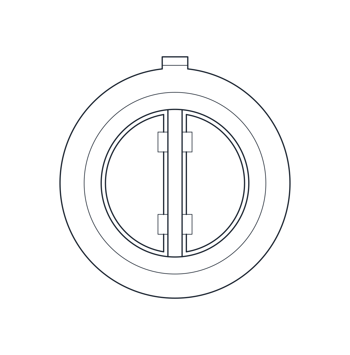
- Units
- Millimetres (INSUNITS 4), drawn at paper size
- Formats
- DWG 2010 · DXF R2010
- Opens in
- AutoCAD and AutoCAD LT 2010 or later, BricsCAD, ZWCAD and DraftSight. The DXF opens in most CAD programs.
- Views
- Plan view + Front elevation
- License
- Free for personal and commercial projects. License
This download holds two DN100 check valves: a flanged PN16 swing check valve with a bolted top cover and a dual plate, or double door, check valve of wafer type. Each comes as a plan block and an elevation block in millimetres at full size, in a DWG for AutoCAD 2010 and later and in a DXF.
Check valve DWG dimensions
Both valves are taken from typical catalogue products. Check the measurements against the datasheet of the valve you buy.
- Swing check valve DN100: 300 mm face to face, 175 mm from the pipe axis to the top of the cover, 220 mm flanges with 8 x M16 to EN 1092 PN16. The block is 300 x 220 x 285 mm.
- Dual plate check valve DN100: 64 mm face to face to EN 558 series 16 and 162 mm outside diameter for PN16. The block is 64 x 162 x 162 mm.
Flange thickness, nuts and the shape of the cover are drawing details.
Check valve drawing in plan and elevation
In the swing check valve the disc, its hinge pin and the bore are hidden lines on layer A-HIDN, with the disc hanging from the hinge near the top of the body. The elevation shows the cover and its bolts, and the plan shows the bolted cover from above. The dual plate valve is a short ring that sits between flanges. In plan it shows the plugs of the hinge pin and the stop pin, and the two plates are hidden lines.
Using the check valve blocks on a pump discharge
A swing check valve needs a horizontal run, or a vertical one with upward flow, and the cover must stay accessible. The dual plate valve saves length, which helps on a tight pump discharge. Like a wafer butterfly valve, it is clamped between the pipe flanges with long bolts, so draw those flanges on each side. Show the flow direction in your drawing, because the blocks carry no arrow. On a P&ID use the check valve symbols, and for the isolating valve that usually follows on the same line, the gate valve block.