Gate Valve CAD Block
Flanged PN16 gate valves in DN50, DN100 and DN200, 150 to 230 mm face to face and 357.5 to 870 mm high.
Gate valve DN50 PN16, flanged, rising stem
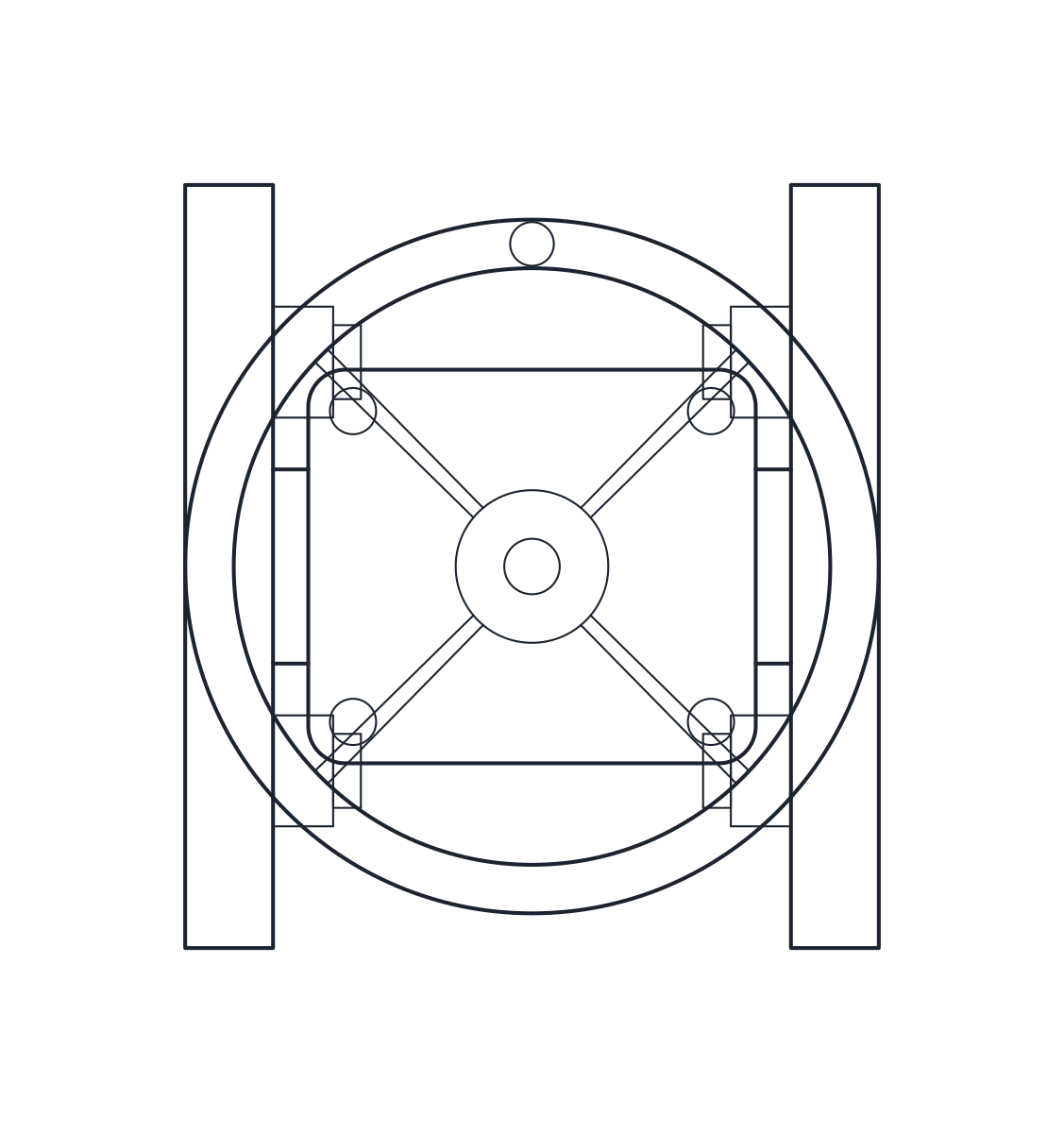
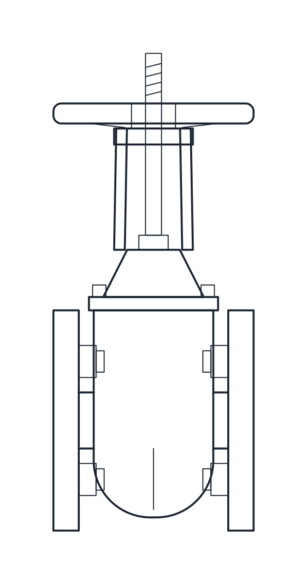
Gate valve DN100 PN16, flanged, rising stem
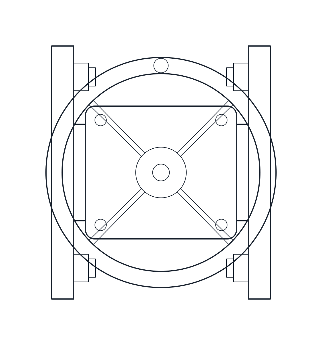
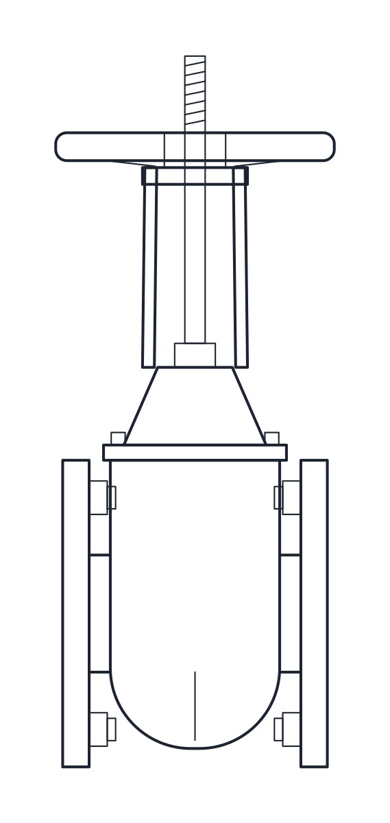
Gate valve DN200 PN16, flanged, rising stem
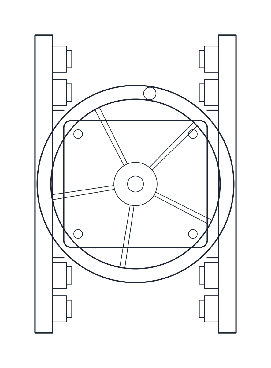
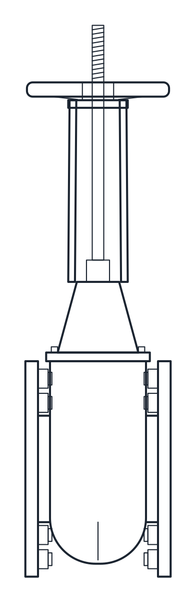
- Units
- Millimetres (INSUNITS 4), drawn at paper size
- Formats
- DWG 2010 · DXF R2010
- Opens in
- AutoCAD and AutoCAD LT 2010 or later, BricsCAD, ZWCAD and DraftSight. The DXF opens in most CAD programs.
- Views
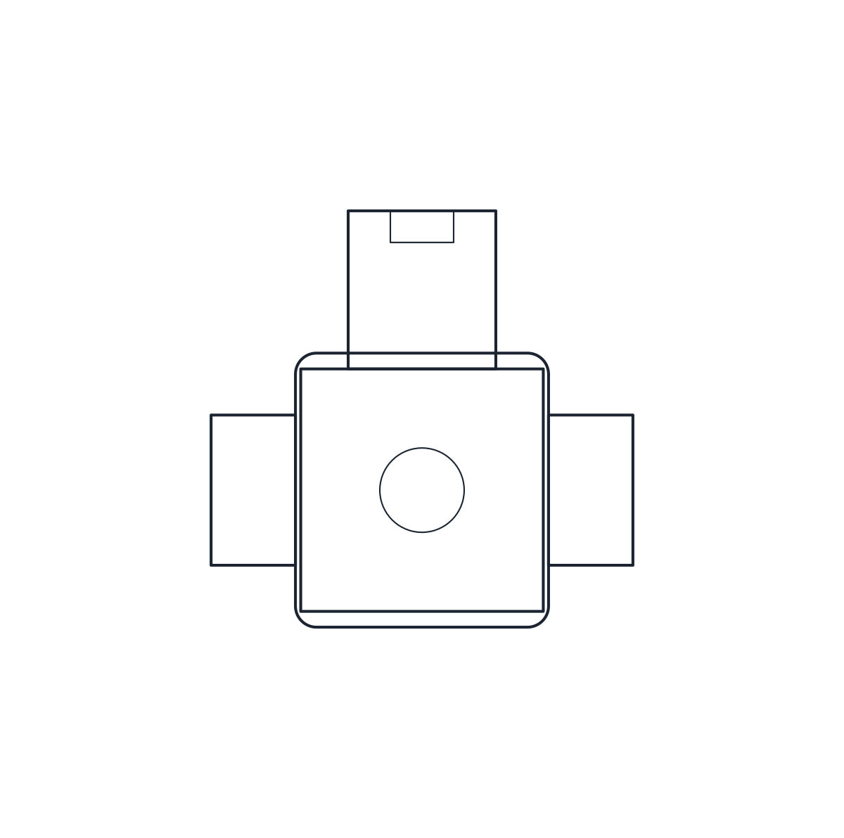
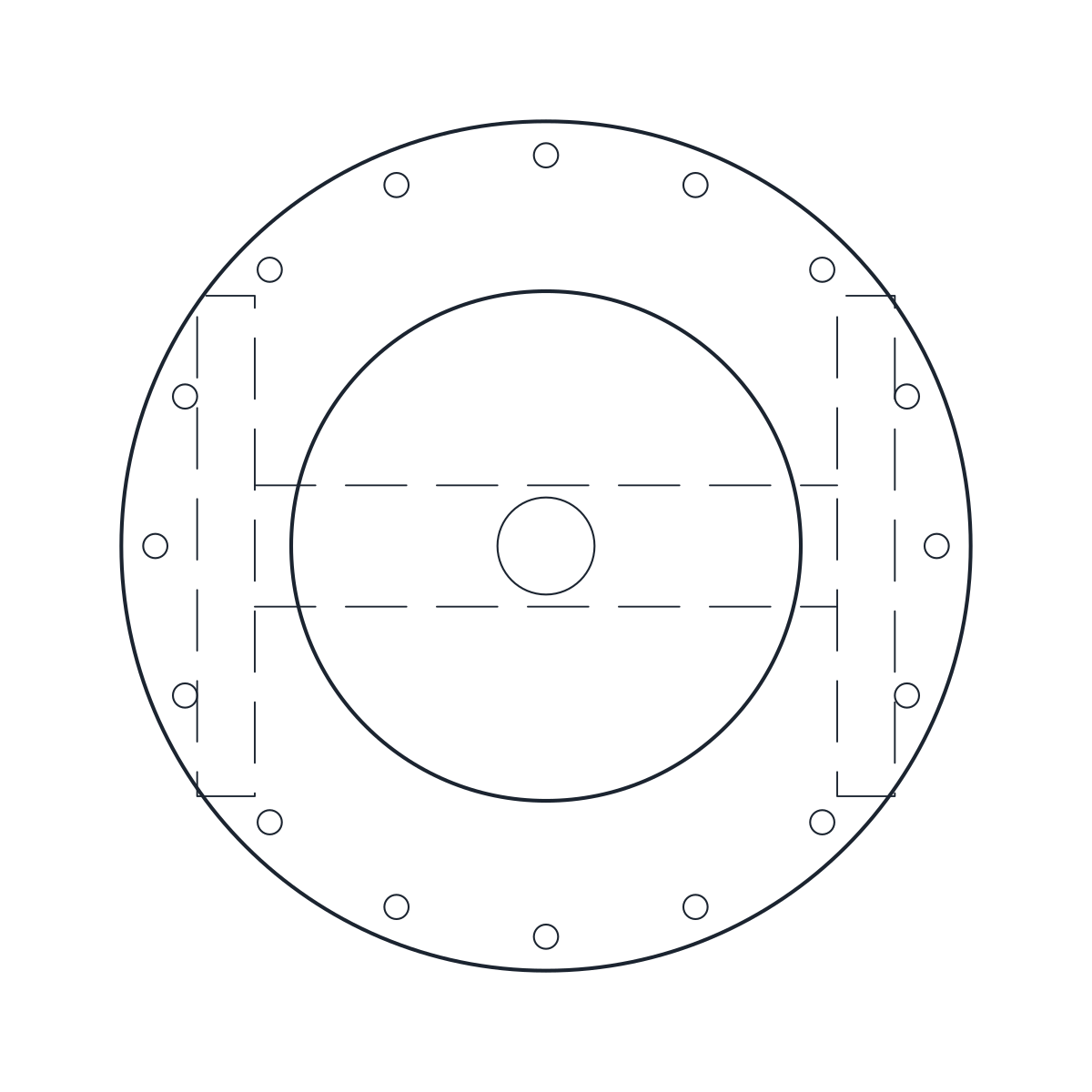
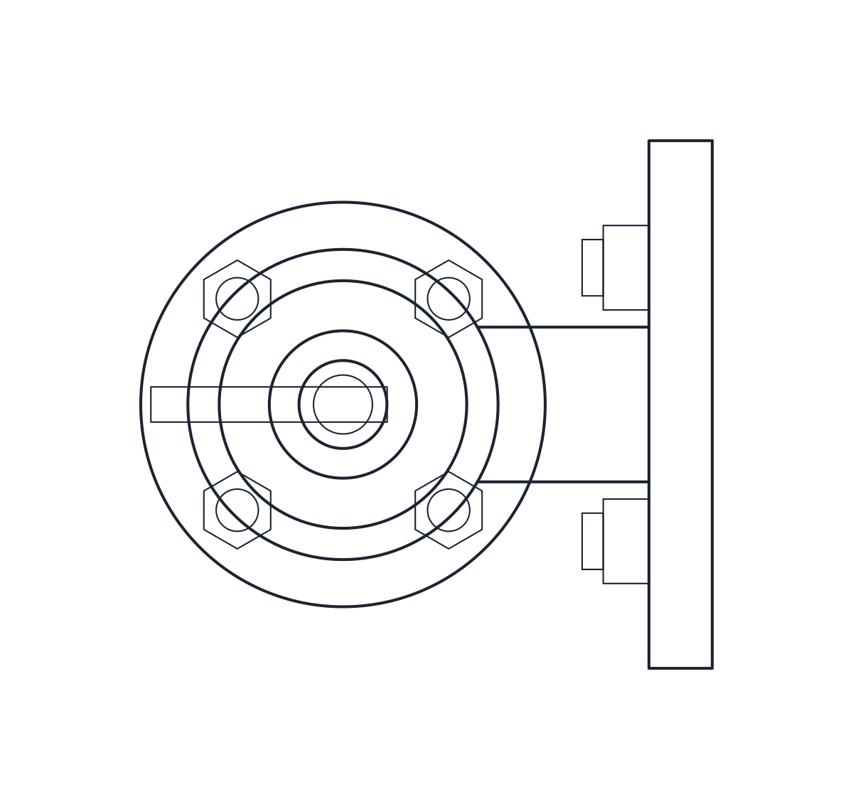
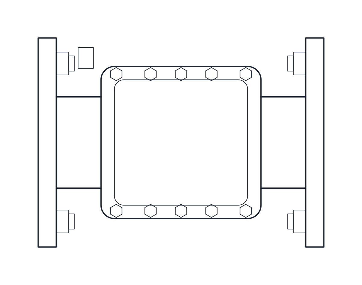
- Plan view + Front elevation
- License
- Free for personal and commercial projects. License
This download holds three flanged gate valves for PN16 lines: DN50, DN100 and DN200. Each one is a cast iron valve with a rising stem, an outside screw and yoke and a handwheel, drawn as a plan block and an elevation block in millimetres at full size. The DWG is saved for AutoCAD 2010 and later, and the DXF opens in any CAD program.
Gate valve DWG dimensions
The valves follow the short face-to-face pattern of DIN 3202 F4. The measurements come from a typical catalogue valve, so check them against the datasheet of the valve you will buy before you fix a layout.
- DN50: 150 mm face to face, 150 mm handwheel, 275 mm from the pipe axis to the top of the stem.
- DN100: 190 mm face to face, 200 mm handwheel, 400 mm from the axis to the top of the stem.
- DN200: 230 mm face to face, 225 mm handwheel, 700 mm from the axis to the top of the stem.
The flanges are drawn to EN 1092 PN16: 165 mm outside diameter with 4 x M16 bolts on DN50, 220 mm with 8 x M16 on DN100 and 340 mm with 12 x M20 on DN200. The datasheet gives the overall height without saying whether it is taken from the axis or from the base, or with the valve open or closed. The block reads it from the axis to the stem tip, so treat the stem height as indicative and confirm it with your supplier. Neck, yoke, nuts and flange thickness are drawing details.
Gate valve drawing in plan and elevation
The elevation shows the body between its two flanges, the bonnet, the yoke, the threaded stem and the handwheel seen edge on. It starts at the lowest point of the flanges, so the overall heights are 357.5, 510 and 870 mm. The plan shows the handwheel with its spokes over the body, and its depth is the flange diameter. The body sits on layer M-VALV and the bolts and small parts on M-VALV-DETL, so you can thin out the detail when you plot at a small scale.
Using the gate valve block in a piping layout
Place the plan block with its flange faces on the pipe run, then keep clear space above the handwheel for the rising stem. On a P&ID the same valve is a symbol, not a scaled outline, and you will find it with the other valve symbols. For throttling duty, where a gate valve is not the usual choice, compare it with the globe valve block.