Globe Valve CAD Block
Flanged PN16 globe valves in DN50 and DN100, 230 and 350 mm face to face with 160 and 225 mm handwheels.
Globe valve DN50 PN16, flanged
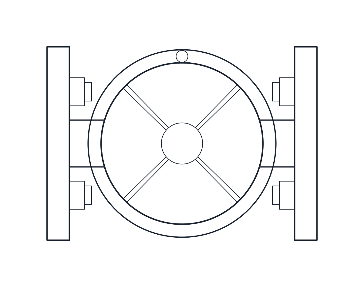
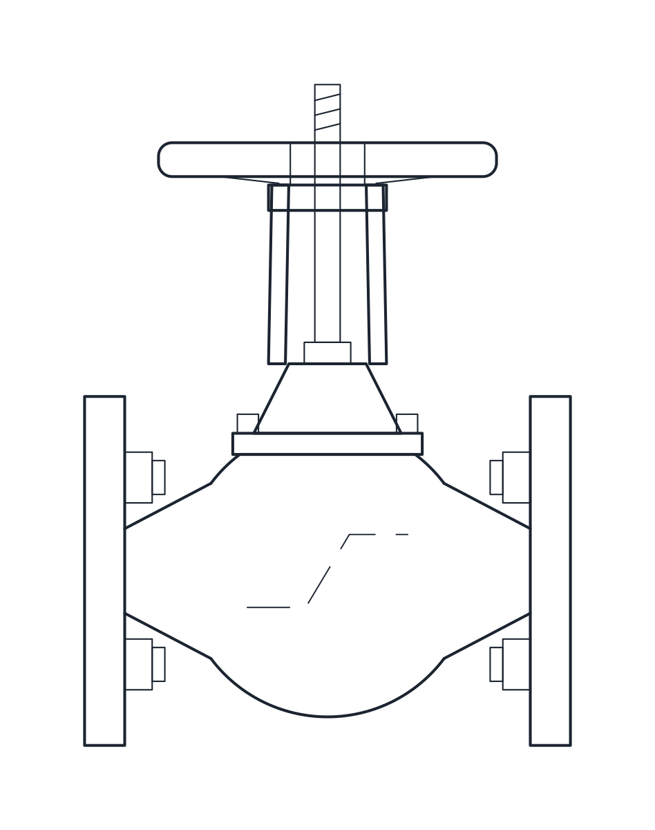
Globe valve DN100 PN16, flanged
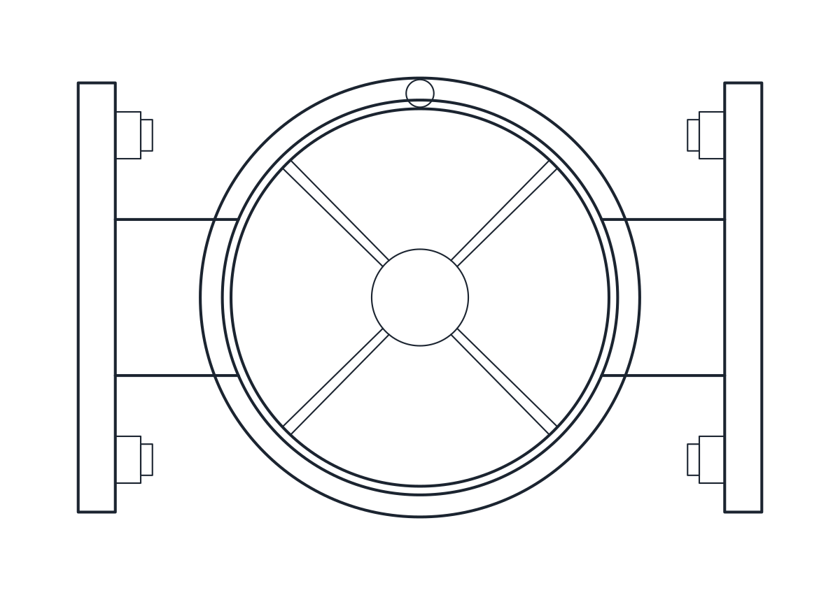
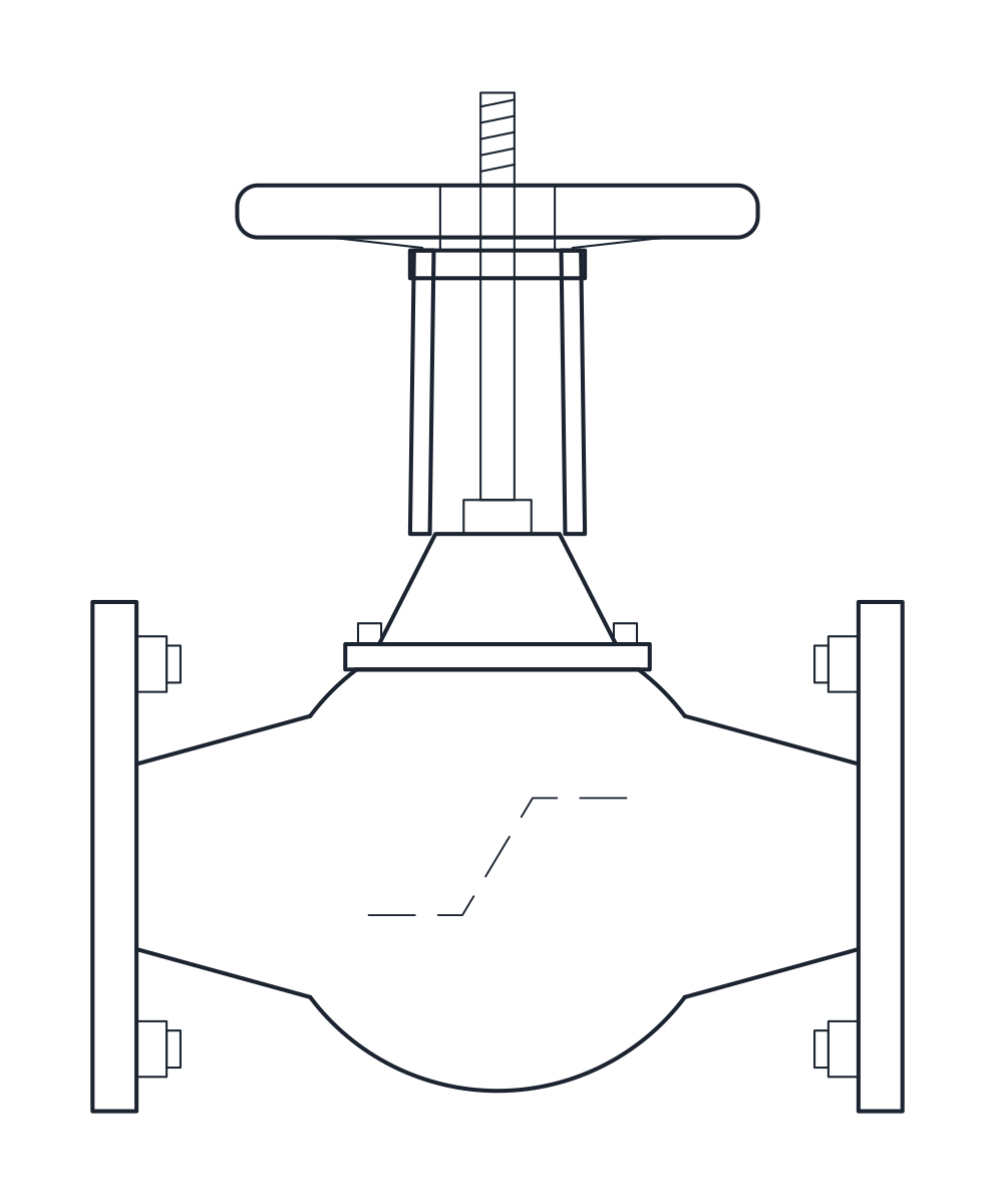
- Units
- Millimetres (INSUNITS 4), drawn at paper size
- Formats
- DWG 2010 · DXF R2010
- Opens in
- AutoCAD and AutoCAD LT 2010 or later, BricsCAD, ZWCAD and DraftSight. The DXF opens in most CAD programs.
- Views
- Plan view + Front elevation
- License
- Free for personal and commercial projects. License
This download holds two flanged globe valves for PN16 lines, DN50 and DN100. Both are straight-pattern cast steel valves with a bolted bonnet, an outside screw and yoke and a handwheel. Each size comes as a plan block and an elevation block, drawn in millimetres at full size, in a DWG for AutoCAD 2010 and later and in a DXF.
Globe valve DWG dimensions
The face-to-face lengths follow EN 558 series 1, the old DIN 3202 F1. The other measurements come from a typical catalogue valve, so check them against the datasheet of the valve you choose.
- DN50: 230 mm face to face, 230 mm from the pipe axis to the top, 160 mm handwheel, 165 mm flanges with 4 x M16.
- DN100: 350 mm face to face, 330 mm from the axis to the top, 225 mm handwheel, 220 mm flanges with 8 x M16.
The flanges are drawn to EN 1092 PN16. The height is read from the pipe axis to the top of the stem. Neck, yoke, nuts and flange thickness are drawing details and should not be used for clearance checks.
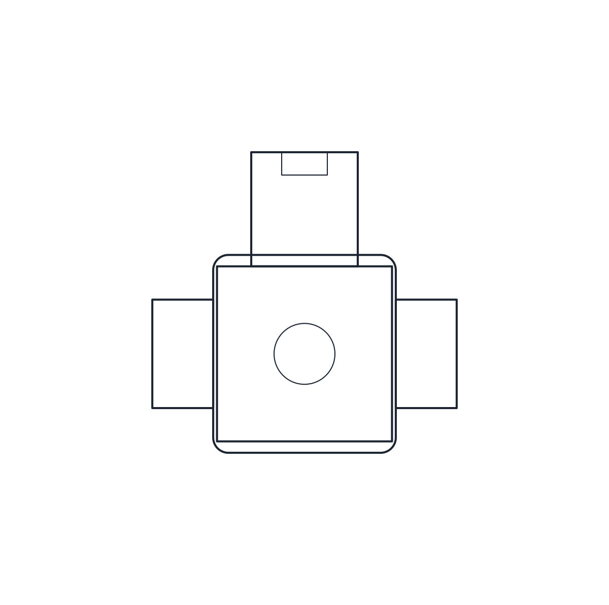
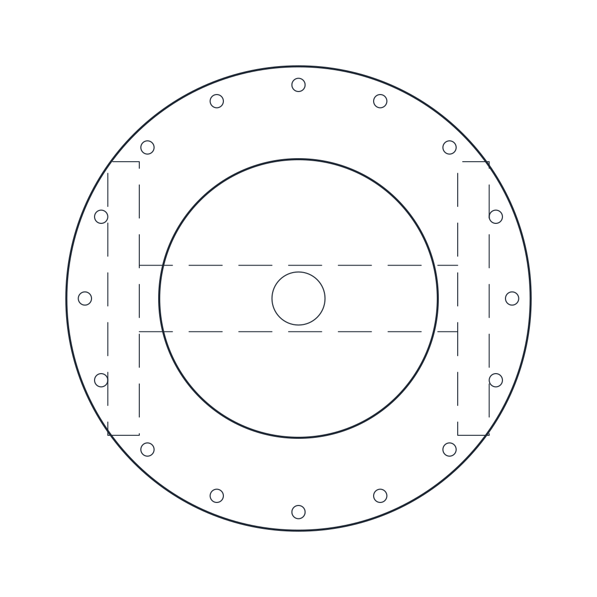
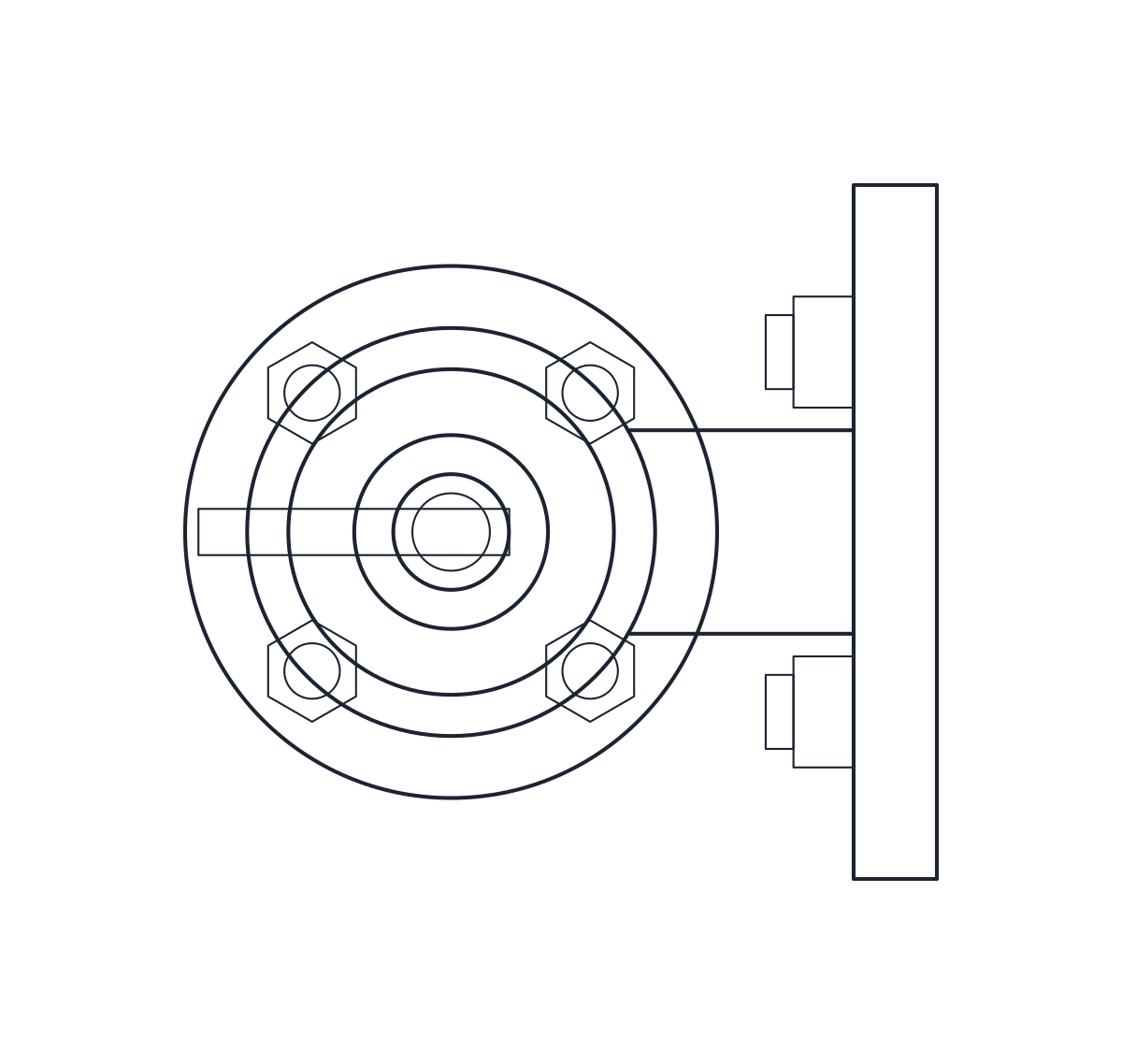
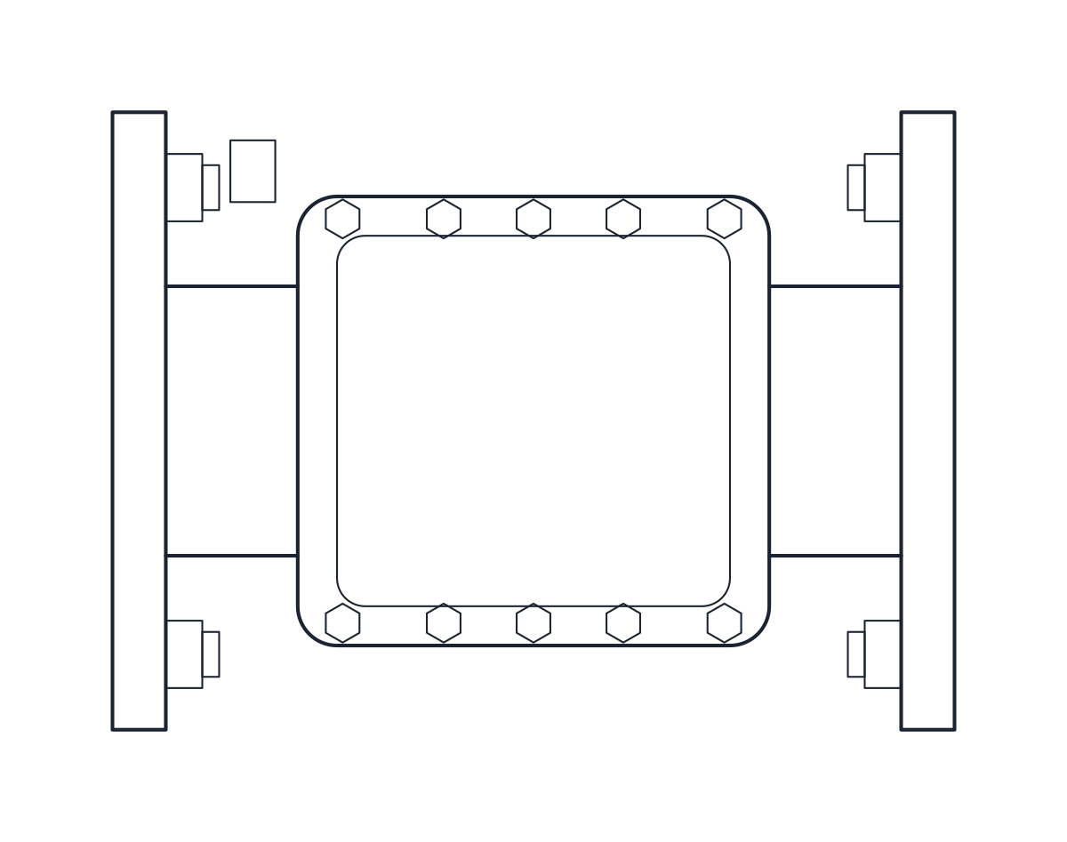
Globe valve drawing in plan and elevation
The elevation shows the round body between the flanges, the bonnet, the yoke and the stem with its handwheel. The S-shaped seat partition inside the body is drawn as a hidden line on layer A-HIDN, which is how a globe valve is told apart from a gate valve in a section. The elevation starts at the lowest point of the flanges, so the blocks are 312.5 and 440 mm high. In plan the handwheel covers most of the body. On DN100 it is wider than the flanges, which is why that plan is 225 mm deep.
Using the globe valve block in a piping layout
Globe valves are long for their size. Allow for the face-to-face length when you space a valve station, and leave room above the handwheel to work it. The body is on layer M-VALV and the detail on M-VALV-DETL. For an isolating valve on the same line, the gate valve block is shorter at the same DN, and on a P&ID the globe valve is drawn with its own mark among the valve symbols.