
CAD libraries
Engineering Drawing Symbols in DWG, DXF and PDF
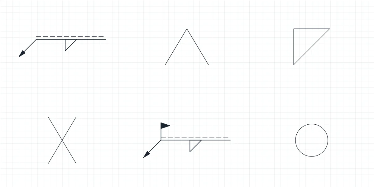
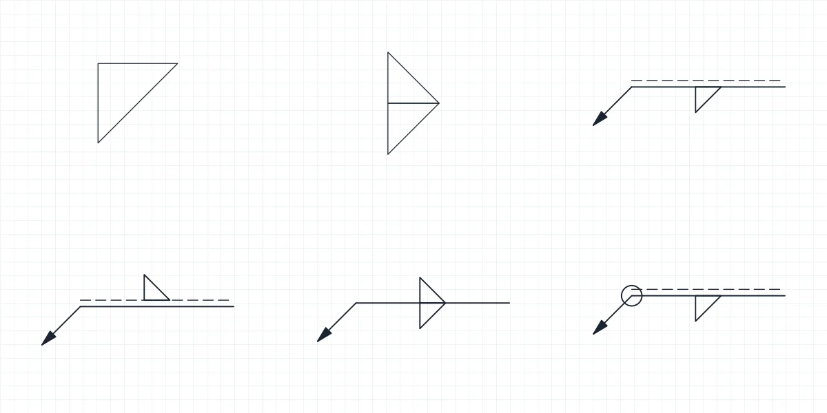
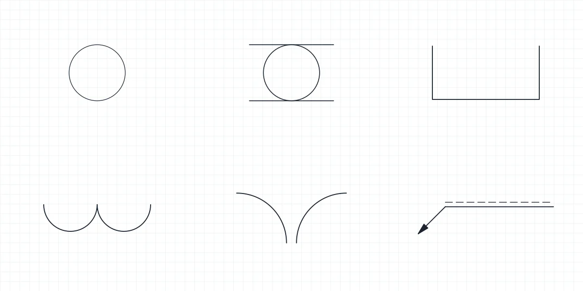
Engineering drawing symbols grouped by discipline. Each discipline has a full library and smaller sets for a single family, such as fillet welds, relays or check valves. Every symbol is a named block in the DWG and DXF, and every set has a PDF sheet that lists its symbols by name.
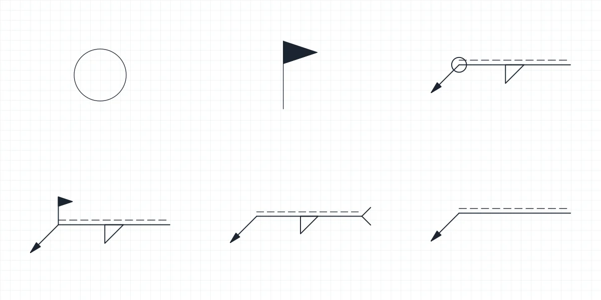
Welding Symbols
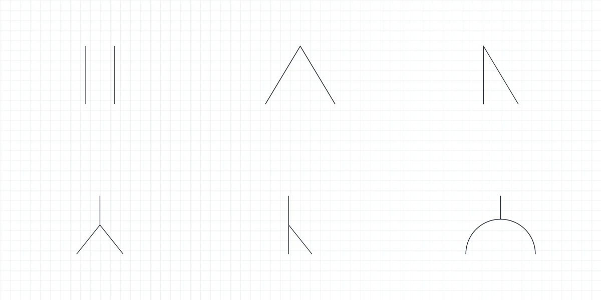
Electrical Schematic Symbols
-
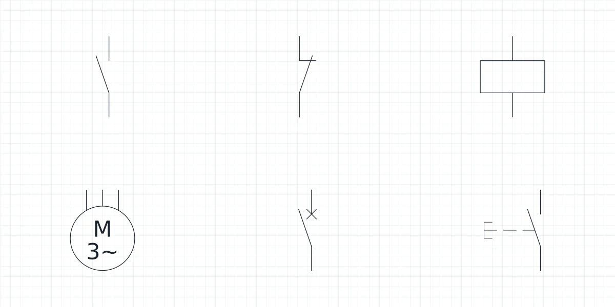 Full library Electrical Schematic Symbols
-
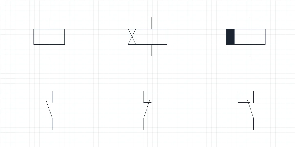 Electrical Schematic Symbols Relay symbol: coil, contact and timer blocks for CAD
-
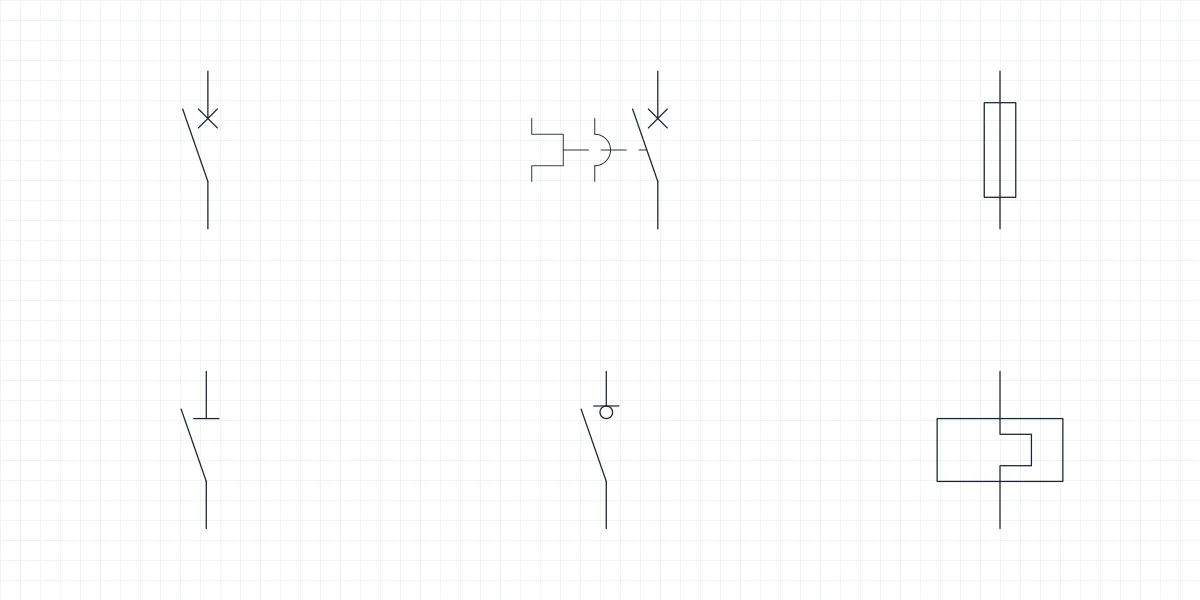 Electrical Schematic Symbols Circuit breaker symbol and fuse blocks for CAD
-
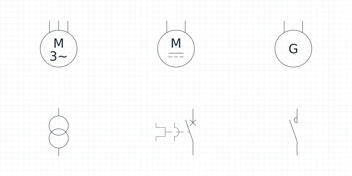 Electrical Schematic Symbols Motor symbol: three phase motor and transformer blocks
-
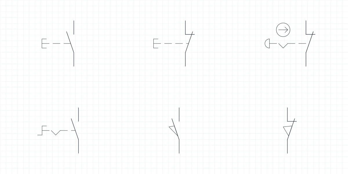 Electrical Schematic Symbols Push button symbol and emergency stop blocks for CAD
-
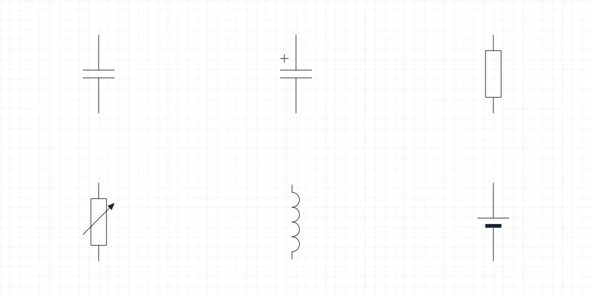 Electrical Schematic Symbols Capacitor symbol and component blocks for CAD
-
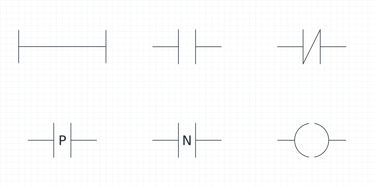 Electrical Schematic Symbols Ladder diagram symbols: IEC 61131-3 blocks for CAD
Hydraulic Symbols
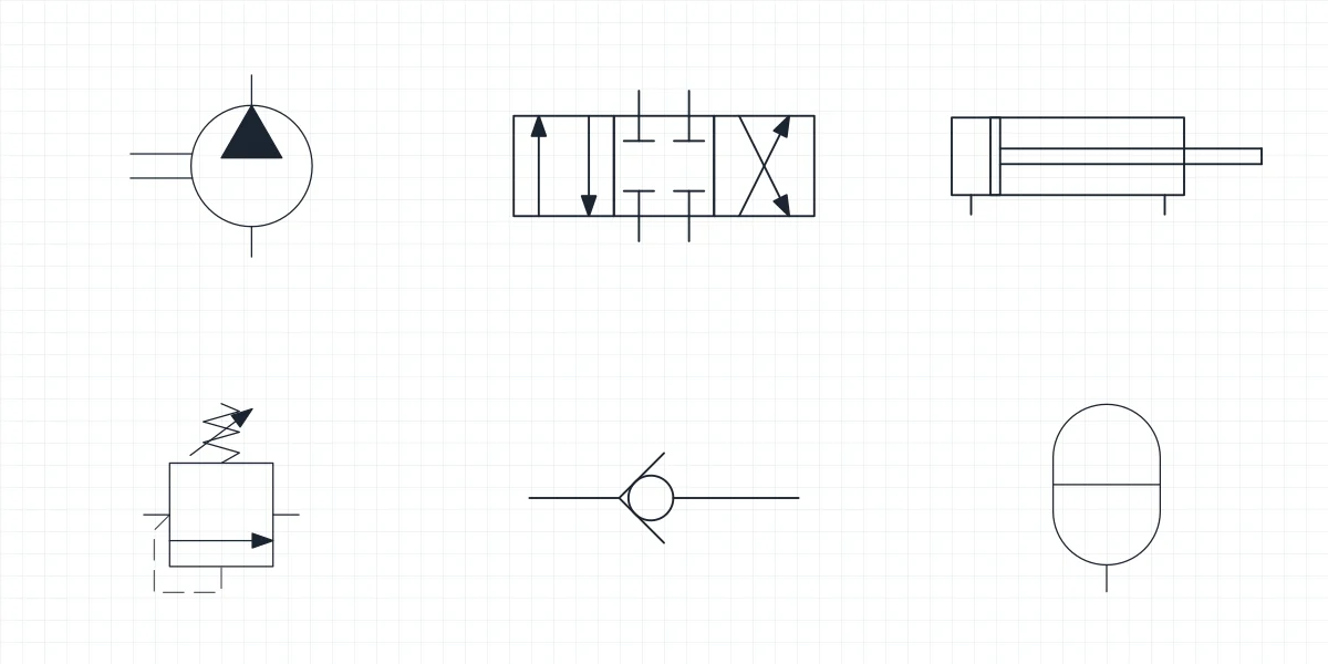
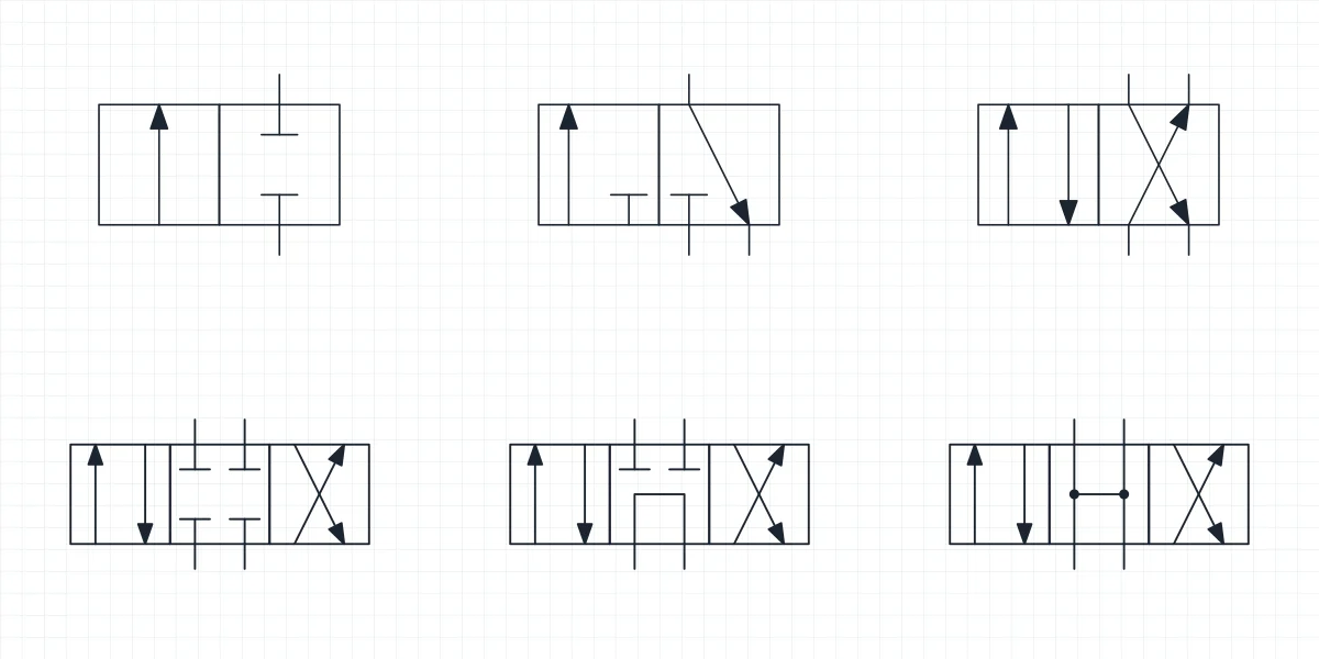
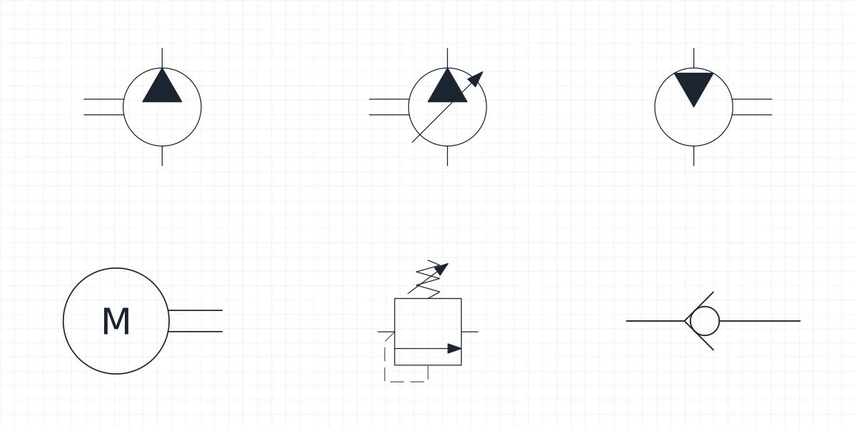
Pneumatic Symbols
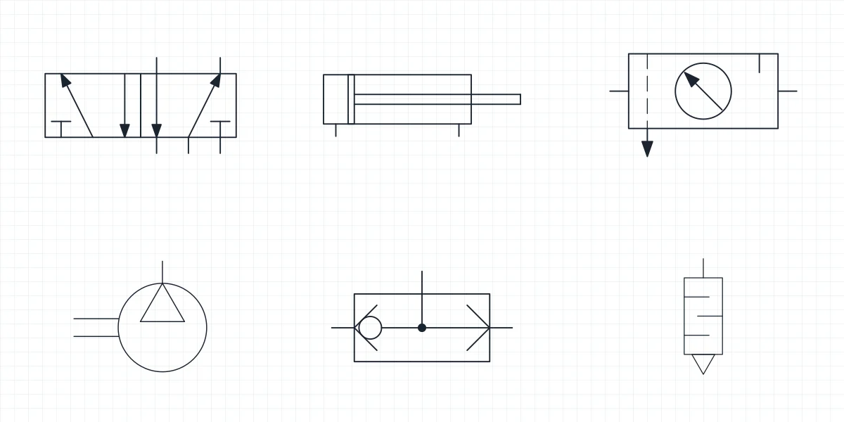
P&ID Symbols
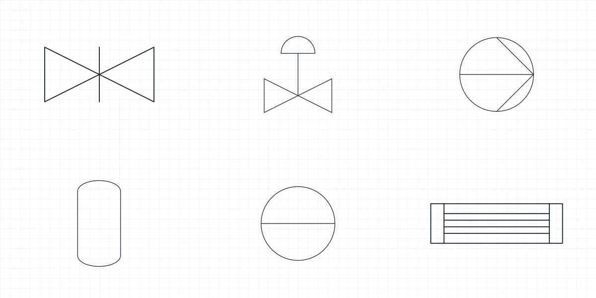
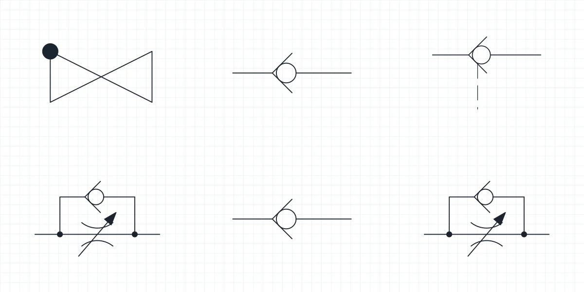
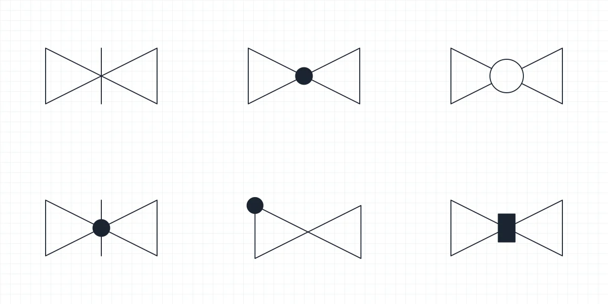
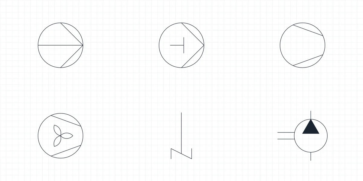
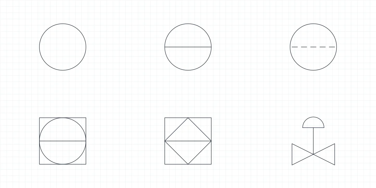
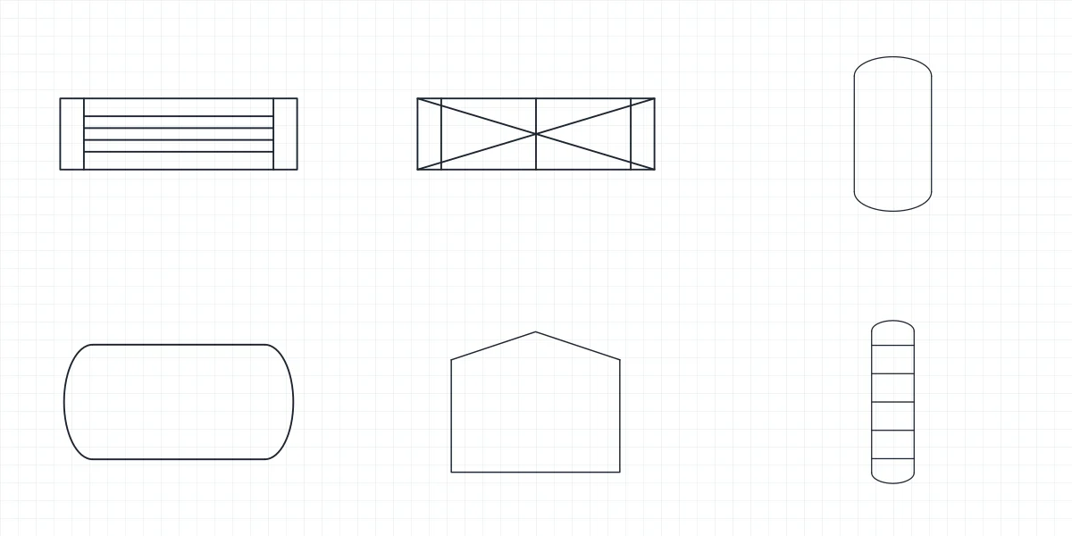
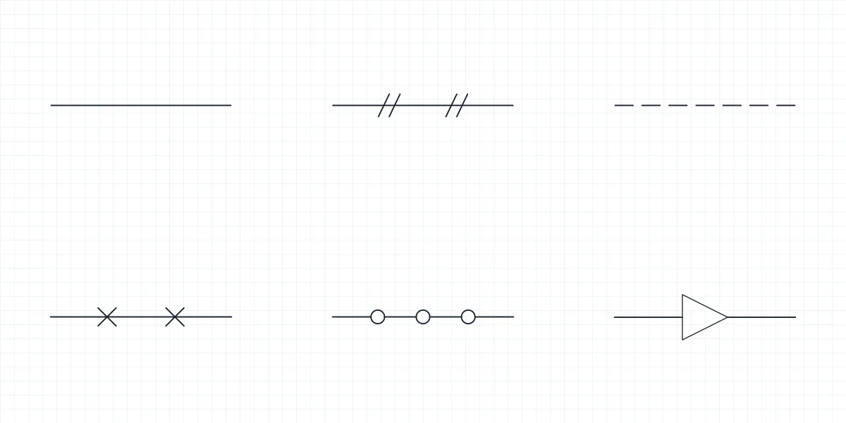
Engineering drawing symbols as blocks, not pictures
Every library on this page is a DWG and a DXF in which each symbol is already a named block, drawn at paper size on a 2.5 mm grid. You insert a fillet weld, a contactor coil or a check valve by name from DesignCenter, and the PDF sheet that comes with each library lists the same symbols on one page for printing.
Which conventions the engineering symbols follow
Welding symbols follow ISO 2553, electrical schematic symbols IEC 60617, hydraulic and pneumatic symbols ISO 1219-1, and P&ID equipment ISO 10628-2 with instrument bubbles after ISA-5.1. The ladder set uses the graphic elements of IEC 61131-3. Each library page says which convention it follows and how the symbols are placed.
Full libraries and smaller symbol sets
The full library of each discipline has every symbol we drew for it. The smaller sets next to it take one family, such as fillet welds, relays or check valves, so the download stays short when that is all you need. The block names are the same in both, so a symbol inserted from either file is identical.