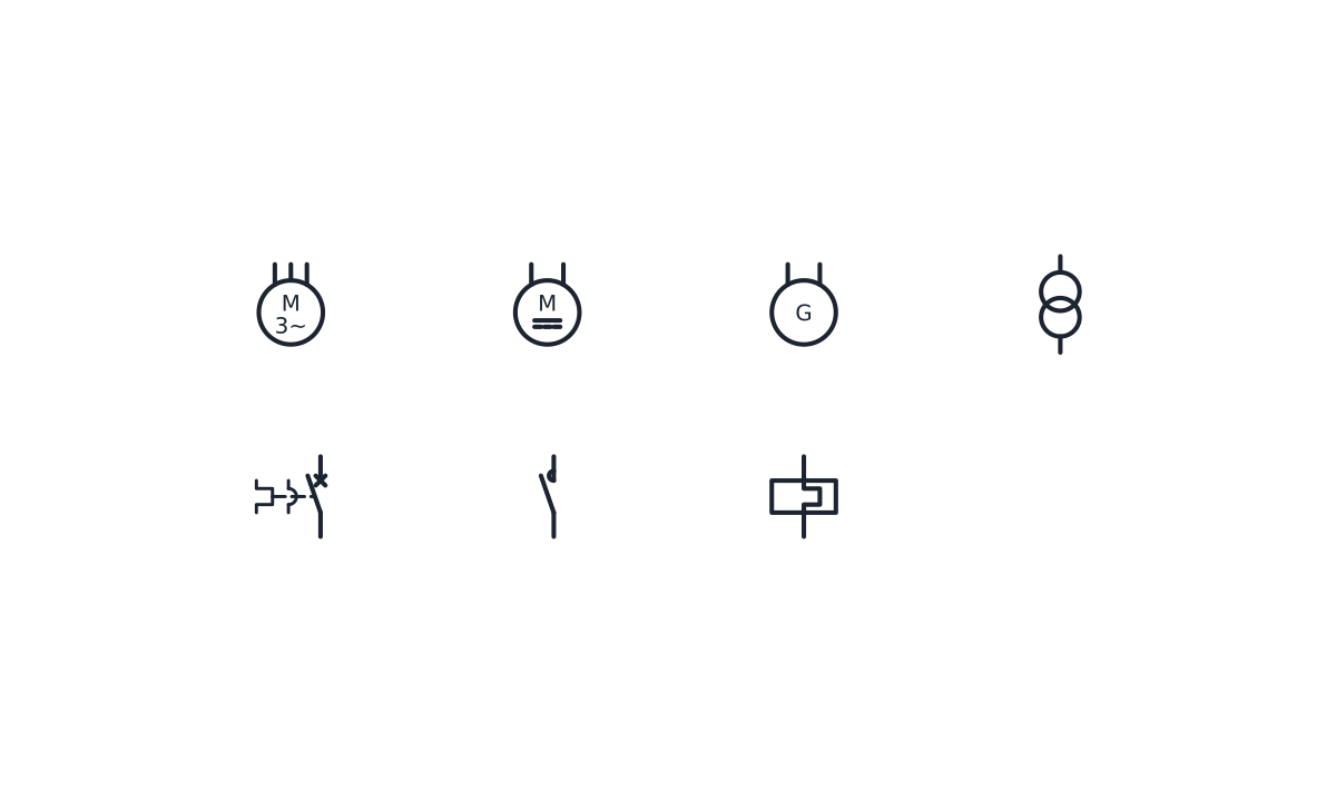
Motor symbol: three phase motor and transformer blocks
Motor, generator and transformer symbols as CAD blocks, with the three devices of a direct-on-line feeder.
Motor symbol library
-
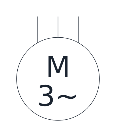
Three-phase motor
A circle with M and 3~ and three supply leads, for an AC three-phase motor such as a squirrel-cage induction motor fed from a starter.
IND_ELECTRICAL_SCHEMATIC_SYMBOLS_MOTOR_THREE_PHASE
-
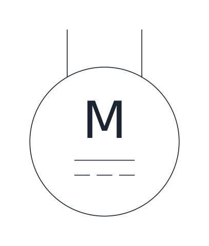
DC motor
A circle with M and the direct current sign, with two supply leads, for a motor fed from a DC source or drive.
IND_ELECTRICAL_SCHEMATIC_SYMBOLS_MOTOR_DC
-
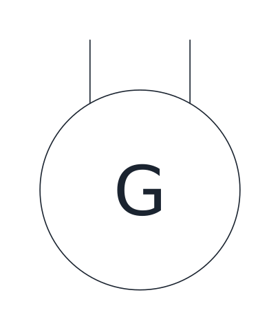
Generator
A circle with G for a rotating generator. Add the current type next to it when the drawing needs it.
IND_ELECTRICAL_SCHEMATIC_SYMBOLS_GENERATOR
-
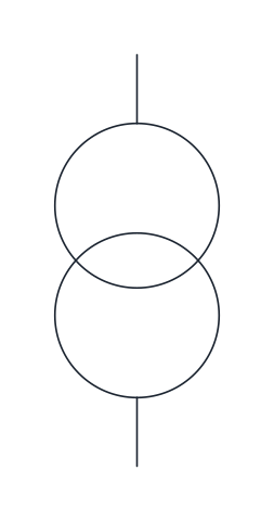
Two-winding transformer
Two overlapping circles for a transformer with separate primary and secondary windings, such as a control-circuit transformer.
IND_ELECTRICAL_SCHEMATIC_SYMBOLS_TRANSFORMER_TWO_WINDING
-
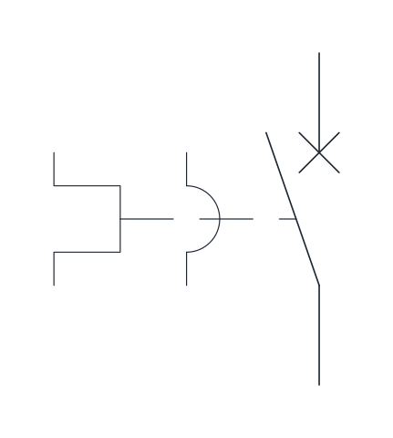
Motor protective circuit breaker
Circuit breaker contact linked to a magnetic release and a thermal release, the usual single-pole representation of a motor protection switch that trips on short circuit and on overload.
IND_ELECTRICAL_SCHEMATIC_SYMBOLS_MOTOR_PROTECTIVE_CIRCUIT_BREAKER
-
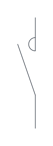
Contactor main contact
A make contact with a semicircle at the fixed contact, marking a main power contact of a contactor rated to switch motor or load currents.
IND_ELECTRICAL_SCHEMATIC_SYMBOLS_CONTACTOR_MAIN_CONTACT_NO
-
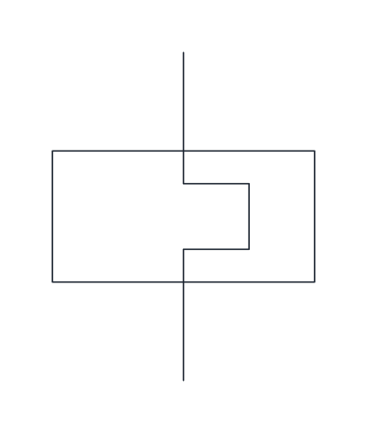
Thermal overload relay
The heating element of a thermal overload relay, drawn in the power circuit between the contactor and the motor. Its auxiliary contacts appear separately in the control circuit.
IND_ELECTRICAL_SCHEMATIC_SYMBOLS_THERMAL_OVERLOAD_RELAY
- Units
- Millimetres (INSUNITS 4), drawn at paper size
- Formats
- DWG 2010 · DXF R2010 · PDF
- Opens in
- AutoCAD and AutoCAD LT 2010 or later, BricsCAD, ZWCAD and DraftSight. The DXF opens in most CAD programs.
- Views
- Sheet
- License
- Free for personal and commercial projects. License
This download holds the motor symbol blocks for IEC schematics: three-phase motor, DC motor, generator and two-winding transformer, plus the three devices that make up a basic motor feeder, the motor protective circuit breaker, the contactor main contact and the thermal overload relay. Each is a named block in the DWG and DXF, with the same names as the full schematic library, and the PDF sheet prints all seven with their names.
Motor symbol in IEC schematics
A rotating machine is a circle with a letter inside: M for a motor, G for a generator. The type of current goes under the letter, 3~ for three-phase alternating current or the direct current sign for a DC machine. The circles here are 10 mm across, large enough to hold the letters at the 2.5 mm text height used in the rest of the library. Contacts and push buttons are on the electrical schematic symbols page.
Three phase motor symbol and its terminals
The three-phase motor block has three supply leads coming in from above, one per phase. On a schematic they are marked with the motor terminal names U1, V1 and W1, and the protective earth conductor is shown going to the motor frame. Whether the windings are connected in star or in delta is set on the terminal board of the motor, so the circuit diagram usually adds a note or a separate detail for it rather than changing the symbol. The DC motor block has two leads, one for each pole of the supply.
A direct-on-line motor feeder with these blocks
The three switching blocks in the set are the ones a simple feeder needs, placed from top to bottom along the power circuit:
- Motor protective circuit breaker, letter Q, which protects the cable and the motor against short circuit and overload
- Contactor main contacts, letter Q, which start and stop the motor on command from the control circuit
- Thermal overload relay, letter F, needed when the feeder is protected by fuses or by a breaker without a thermal release
- Motor, letter M
The protective symbols are covered in more depth on the circuit breaker symbol page, and the coil that drives the contactor on the relay symbol page.
Transformer symbol and generator symbol
The two-winding transformer is drawn as two overlapping circles, one for each winding. In a control panel it is most often the control transformer that steps the supply down for the control circuit, and it takes the letter T. The generator block has the letter G and two leads, with no current type marked, so you can add it next to the circle when the drawing needs it.
Placing motor symbol blocks on the drawing
Motors, the generator and the transformer have their base point at the centre of the body. The in-line devices of the feeder work differently: their base point is the lower terminal and the upper terminal is 12.5 mm above it. All of them sit on the same 2.5 mm grid, so a feeder drawn with vertical wires lines up without moving anything by hand.
Machine symbols are based on IEC 60617. The standard is a paid IEC product, so go to the source if a project specification asks for a particular symbol entry.