Welding Symbols
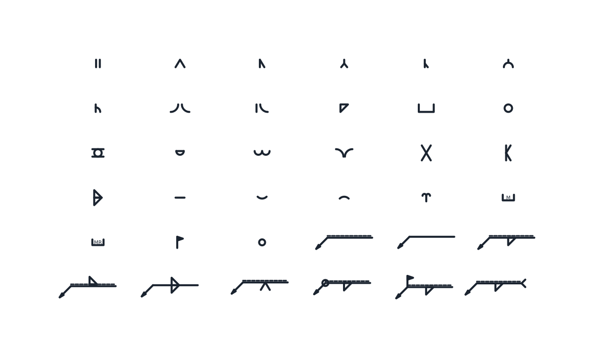
36 welding symbols drawn after ISO 2553: elementary and supplementary symbols and ready callouts in system A, each one its own block.
Welding Symbols library
Elementary welding symbols
-
Square butt weld
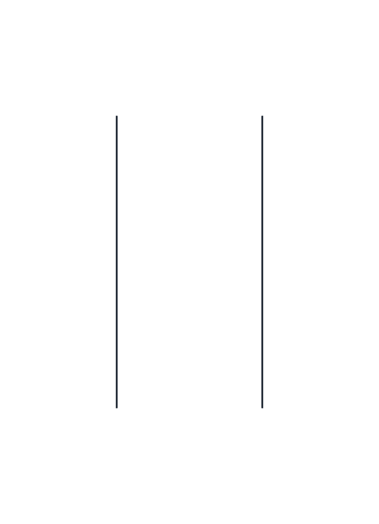
Two parallel strokes for a butt weld between square-cut edges with no groove preparation. Common on thin plate, where the edges are welded through without bevelling.
IND_WELDING_SYMBOLS_SQUARE_BUTT
-
Single-V butt weld
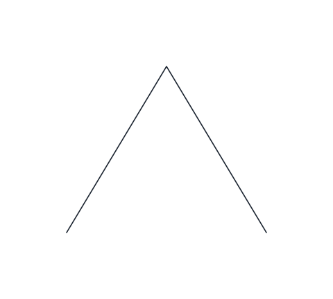
A V whose point sits on the reference line, for a butt weld where both edges are bevelled to form a V groove. Unless the symbol carries a penetration depth, the weld is read as full penetration.
IND_WELDING_SYMBOLS_SINGLE_V_BUTT
-
Single-bevel butt weld
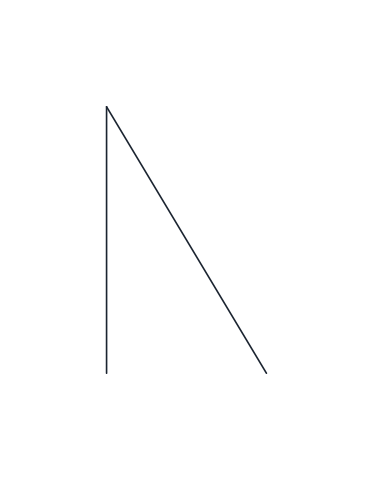
A vertical stroke with one inclined stroke, for a butt or T joint where only one member is bevelled. The vertical stroke always stays on the left and the arrow points at the bevelled member.
IND_WELDING_SYMBOLS_SINGLE_BEVEL_BUTT
-
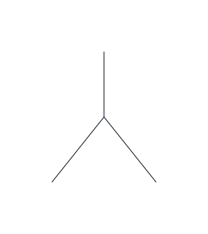
Single-V butt weld with broad root face
A Y shape: a V groove whose edges keep a straight root face below the bevel. Used for thicker plate where the root is left unbevelled to support the first run.
IND_WELDING_SYMBOLS_SINGLE_V_BROAD_ROOT
-
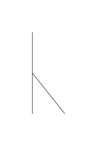
Single-bevel butt weld with broad root face
A vertical stroke with a short inclined stroke starting halfway up, for a single-bevel preparation that keeps a root face. The vertical stroke stays on the left.
IND_WELDING_SYMBOLS_SINGLE_BEVEL_BROAD_ROOT
-
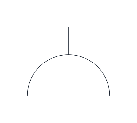
Single-U butt weld
A stem with a semicircular cup, for a butt weld whose groove has a rounded bottom on both edges. The U preparation needs less filler metal than a V on thick sections.
IND_WELDING_SYMBOLS_SINGLE_U_BUTT
-
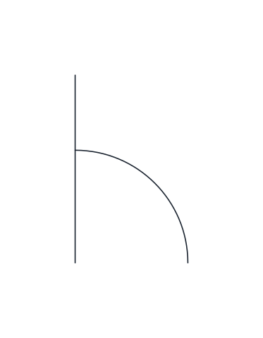
Single-J butt weld
A vertical stroke with a quarter arc, for a joint where one member is machined to a J profile and the other is left square. The arrow points at the prepared member.
IND_WELDING_SYMBOLS_SINGLE_J_BUTT
-
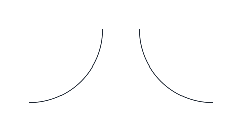
Flare-V butt weld
Two facing arcs for a groove formed between two curved surfaces, such as two round bars or two formed edges laid side by side.
IND_WELDING_SYMBOLS_FLARE_V
-
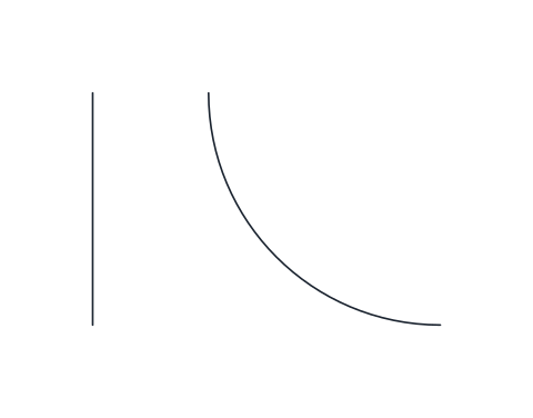
Flare-bevel butt weld
A vertical stroke and one arc, for a groove between a curved surface and a flat one, such as a bar or tube welded against a plate.
IND_WELDING_SYMBOLS_FLARE_BEVEL
-
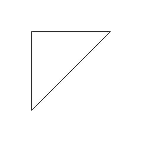
Fillet weld
A right triangle with its vertical leg on the left, for a weld of roughly triangular section in a T, lap or corner joint. The throat thickness (a) or leg length (z) is written to its left.
IND_WELDING_SYMBOLS_FILLET
-
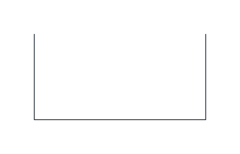
Plug or slot weld
An open rectangle for a weld that fills a round hole or an elongated slot in one member to join it to the member underneath.
IND_WELDING_SYMBOLS_PLUG_SLOT
-

Spot weld
A circle for a spot weld. Drawn centred on the reference line, as ISO 2553 shows it for resistance spot welding; a fusion spot weld sits on the arrow side or the other side instead.
IND_WELDING_SYMBOLS_SPOT
-
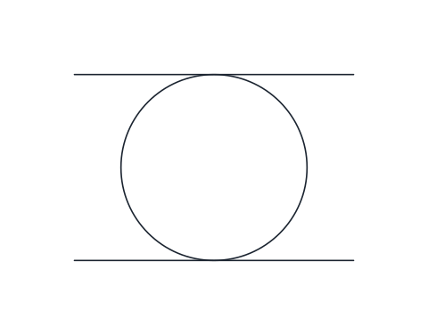
Seam weld
A circle with two parallel lines through it, for a continuous seam made by overlapping spots, usually by resistance welding with roller electrodes. Drawn centred on the reference line.
IND_WELDING_SYMBOLS_SEAM
-
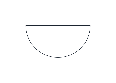
Backing run
A half circle with its flat side on the reference line, for a run laid on the root side of a butt weld. It is placed on the side opposite the main weld symbol.
IND_WELDING_SYMBOLS_BACKING_RUN
-
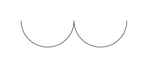
Surfacing (overlay)
Two adjacent half circles for weld metal deposited on a surface rather than in a joint, for example hardfacing or buttering before welding.
IND_WELDING_SYMBOLS_SURFACING
-
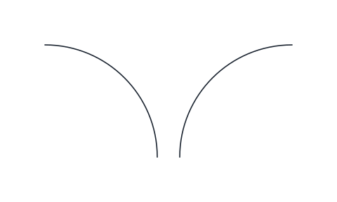
Flanged butt or corner weld
Two curved strokes for a joint whose edges are turned up into flanges and fused together, typical of thin sheet. Known in US practice as an edge-flange weld.
IND_WELDING_SYMBOLS_EDGE_FLANGE
-
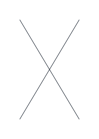
Double-V butt weld
An X formed by a V on each side of the reference line, for a butt weld prepared and welded from both sides. With identical welds on both sides the dashed identification line is left out.
IND_WELDING_SYMBOLS_DOUBLE_V_BUTT
-
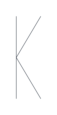
Double-bevel butt weld
A K shape: one member bevelled from both sides, often in a T joint. The vertical stroke runs through the reference line and stays on the left.
IND_WELDING_SYMBOLS_DOUBLE_BEVEL_BUTT
-
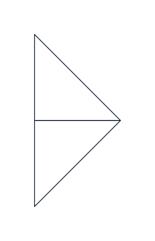
Double fillet weld
A fillet triangle on each side of the reference line, for fillet welds on both sides of a T joint. With equal welds on both sides the dashed identification line is omitted.
IND_WELDING_SYMBOLS_DOUBLE_FILLET
Supplementary welding symbols
-
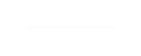
Flush (flat) finish
A straight line added to the weld symbol to ask for a flat weld face, usually dressed flush by grinding or machining.
IND_WELDING_SYMBOLS_FLUSH
-
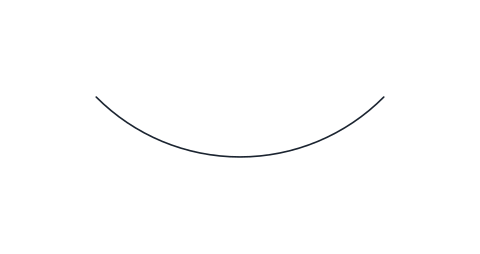
Convex weld face
An arc bulging away from the reference line, added to the weld symbol to ask for a convex weld profile.
IND_WELDING_SYMBOLS_CONVEX
-
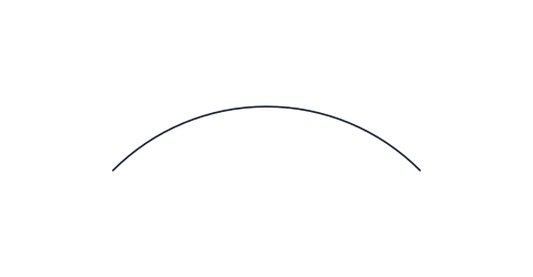
Concave weld face
An arc curving towards the reference line, added to the weld symbol to ask for a concave weld profile, most often on fillet welds.
IND_WELDING_SYMBOLS_CONCAVE
-
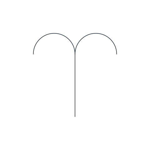
Toes blended smoothly
Asks for the weld toes to blend smoothly into the parent metal, which may mean dressing them. Typical on fatigue-loaded joints.
IND_WELDING_SYMBOLS_TOES_BLENDED
-
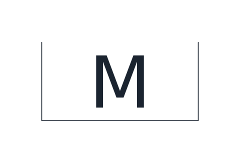
Permanent backing strip (M)
A box with the letter M, placed on the root side to show that a backing strip is used and stays in place after welding.
IND_WELDING_SYMBOLS_PERMANENT_BACKING_STRIP
-
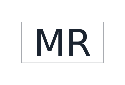
Removable backing strip (MR)
A box with the letters MR, placed on the root side to show that a backing strip is used and removed after welding.
IND_WELDING_SYMBOLS_REMOVABLE_BACKING_STRIP
-
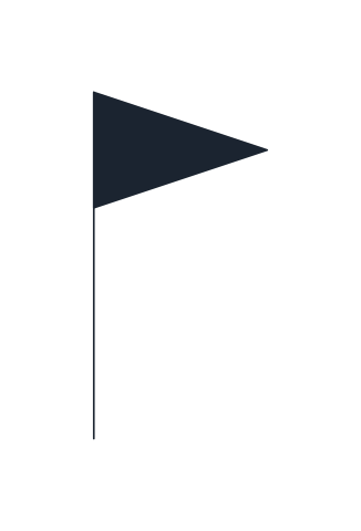
Field weld (site weld)
A flag at the junction of the arrow line and the reference line, meaning the weld is made on site or at the place of erection rather than in the shop.
IND_WELDING_SYMBOLS_FIELD_WELD
-

Weld all around
A circle at the junction of the arrow line and the reference line, meaning the weld runs continuously around the whole joint, for example around a tube or a bracket.
IND_WELDING_SYMBOLS_WELD_ALL_AROUND
Complete welding symbols with arrow and reference line
-
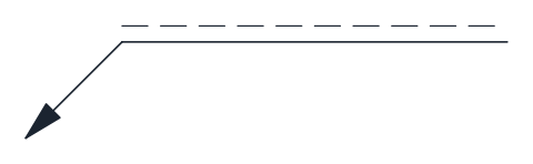
Reference line, system A
Arrow line with the dual reference line of ISO 2553 system A: a continuous line for the arrow side and a dashed identification line for the other side. The block's base point is the arrowhead tip.
IND_WELDING_SYMBOLS_REFERENCE_LINE_SYSTEM_A
-
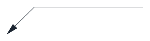
Reference line, system B
Arrow line with the single reference line of system B, where a symbol below the line means the arrow side and one above it the other side, as in AWS A2.4.
IND_WELDING_SYMBOLS_REFERENCE_LINE_SYSTEM_B
-
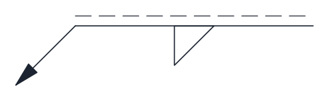
Fillet weld, arrow side
Complete system A welding symbol with the fillet triangle on the continuous line, so the weld is made on the side the arrow touches. Attributes SIZE and LENGTH take the weld size and length.
IND_WELDING_SYMBOLS_FILLET_ARROW_SIDE
-
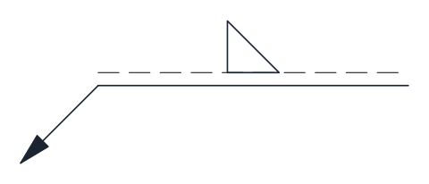
Fillet weld, other side
Complete system A welding symbol with the fillet triangle on the dashed identification line, so the weld is made on the side opposite the arrow.
IND_WELDING_SYMBOLS_FILLET_OTHER_SIDE
-
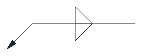
Fillet weld, both sides
Complete welding symbol with fillet triangles on both sides of the reference line and no dashed line, as used for symmetrical welds. Separate attributes take the size and length for each side.
IND_WELDING_SYMBOLS_FILLET_BOTH_SIDES
-
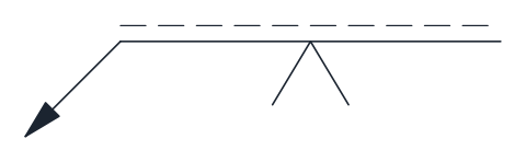
Single-V butt weld, arrow side
Complete system A welding symbol with a single-V butt weld on the arrow side. SIZE can take a penetration depth (s); left empty, the butt weld is full penetration.
IND_WELDING_SYMBOLS_SINGLE_V_ARROW_SIDE
-
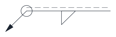
Fillet weld all around
Arrow-side fillet weld with the all-around circle at the junction, for a fillet that runs around the full perimeter of the part.
IND_WELDING_SYMBOLS_FILLET_ALL_AROUND
-
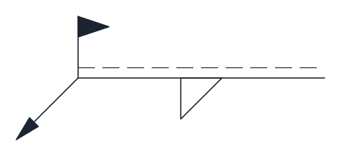
Fillet weld made on site
Arrow-side fillet weld with the field weld flag at the junction, for a fillet weld made during erection rather than in the shop.
IND_WELDING_SYMBOLS_FILLET_FIELD_WELD
-
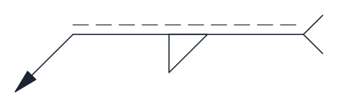
Welding symbol with tail and process
Arrow-side fillet weld with a tail at the end of the reference line. The PROCESS attribute takes the process reference number from ISO 4063, and the tail can also hold other complementary information.
IND_WELDING_SYMBOLS_TAIL_WITH_PROCESS
- Units
- Millimetres (INSUNITS 4), drawn at paper size
- Formats
- DWG 2010 · DXF R2010 · PDF
- Opens in
- AutoCAD and AutoCAD LT 2010 or later, BricsCAD, ZWCAD and DraftSight. The DXF opens in most CAD programs.
- Views
- Sheet
- License
- Free for personal and commercial projects. License
The library below draws the welding symbols of ISO 2553 as CAD blocks: the elementary symbols that describe the joint, the supplementary symbols for finish and shape, and complete callouts with arrow, reference line and tail. Each one is a separate block in the DWG and DXF, and the PDF sheet prints the whole welding symbols chart on one A4 page.
How to read welding symbols on a drawing
A welding symbol is a small sentence made of fixed parts. The arrow line touches the joint. The reference line runs horizontally from the end of the arrow and carries everything else. The elementary symbol sits on the reference line and shows the shape of the weld seen in section: a triangle for a fillet, a V for a single V butt, a single slanted line for a bevel. Sizes go to the left of the symbol and lengths to the right. A fork at the far end, the tail, holds extra information such as the welding process.
The side of the reference line on which the symbol sits tells the welder which side of the joint to weld. That is the part people misread most often, and it is where the two systems of ISO 2553 differ.
Arrow side and other side in ISO 2553 welding symbols: system A and system B
In system A the reference line is doubled: a continuous line and a dashed identification line next to it. A symbol on the continuous line means the weld goes on the arrow side of the joint. A symbol on the dashed line means the other side. In system B there is a single continuous line, as in the US convention of AWS A2.4: a symbol below the line means the arrow side and a symbol above it means the other side. Symmetrical welds, such as a double fillet, sit across the line and need no identification line in either system.
The library includes an empty reference line for each system, so you can build your own callout, and ready-made callouts drawn in system A.
Fillet weld symbol and groove weld symbols
The fillet weld symbol is a right triangle with its vertical leg on the left, whatever the direction of the joint. In ISO practice the size in front of it carries a letter: a for the throat thickness and z for the leg length, so a5 and z7 describe two different welds. US drawings give the leg size without a letter, which is one more reason to know which convention a drawing follows.
Butt welds, called groove welds in the US, have one symbol per edge preparation: square, single V, single bevel, V or bevel with a broad root face, U and J. Doubled preparations welded from both sides, such as the double V and the double bevel, are drawn on both sides of the reference line.
Supplementary welding symbols and the tail
Supplementary symbols are added to the elementary one. A straight line over it asks for a flush surface, an arc asks for a convex or concave profile, and a small circle at the junction of arrow and reference line means the weld runs all around the part. A flag at the same point marks a weld made on site rather than in the workshop. Backing strips, permanent or removable, have their own marks.
The tail carries the process number from ISO 4063, for example 111 for manual metal arc welding, 135 for MAG welding with a solid wire and 141 for TIG welding, and it can also point to a welding procedure specification.
Using the welding symbols in AutoCAD
Every symbol is drawn at paper size on a 2.5 mm grid, 5 mm high for one-sided symbols and 10 mm for symbols that cross the line. The elementary symbols hang below the line, in the arrow-side position of system A, with the base point at their centre or at the foot of the vertical stroke for the asymmetric ones. The complete callouts are placed by the tip of the arrow. Insert it from DesignCenter (ADCENTER), or copy the blocks you use most into your template. The complete callouts carry two attributes, SIZE and LENGTH, that AutoCAD asks for on insert. If your drawing is plotted at a scale other than 1:1, scale the block by the plot factor so the symbol prints at the same size as your text.
The shapes follow ISO 2553:2019. The standard is sold by ISO and is not reproduced here. If a contract or a client standard names a particular edition, check the symbols against it before issuing drawings.
Welding symbol libraries by weld type
- Fillet weld symbol: CAD blocks with a and z sizes: Ten ISO 2553 fillet weld blocks, from the plain triangle to complete callouts with size and length attributes.
- Groove weld symbols: butt weld blocks for CAD: Fifteen groove and butt weld symbols as CAD blocks, with notes on bevel direction and penetration.
- Spot weld symbol and seam weld blocks for CAD: Spot, seam, plug, surfacing and flanged weld symbols as CAD blocks, with both ISO 2553 reference lines.
- Weld all around symbol and field weld blocks: The all around circle, the field weld flag and the tail as CAD blocks that snap onto any welding callout.