Fillet weld symbol: CAD blocks with a and z sizes
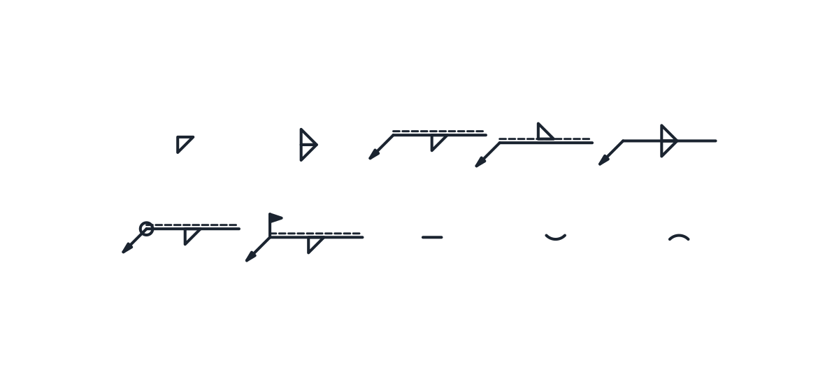
Ten ISO 2553 fillet weld blocks, from the plain triangle to complete callouts with size and length attributes.
Fillet weld symbol library
-
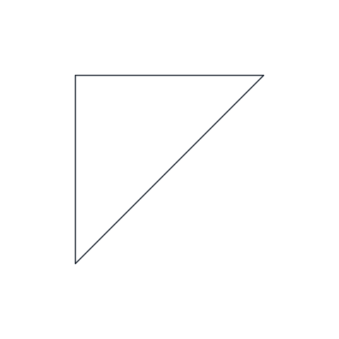
Fillet weld
A right triangle with its vertical leg on the left, for a weld of roughly triangular section in a T, lap or corner joint. The throat thickness (a) or leg length (z) is written to its left.
IND_WELDING_SYMBOLS_FILLET
-
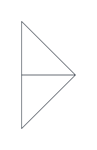
Double fillet weld
A fillet triangle on each side of the reference line, for fillet welds on both sides of a T joint. With equal welds on both sides the dashed identification line is omitted.
IND_WELDING_SYMBOLS_DOUBLE_FILLET
-
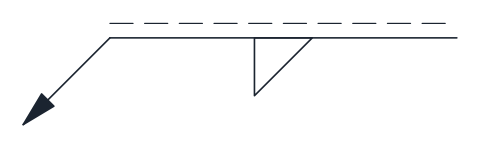
Fillet weld, arrow side
Complete system A welding symbol with the fillet triangle on the continuous line, so the weld is made on the side the arrow touches. Attributes SIZE and LENGTH take the weld size and length.
IND_WELDING_SYMBOLS_FILLET_ARROW_SIDE
-
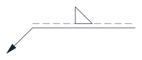
Fillet weld, other side
Complete system A welding symbol with the fillet triangle on the dashed identification line, so the weld is made on the side opposite the arrow.
IND_WELDING_SYMBOLS_FILLET_OTHER_SIDE
-
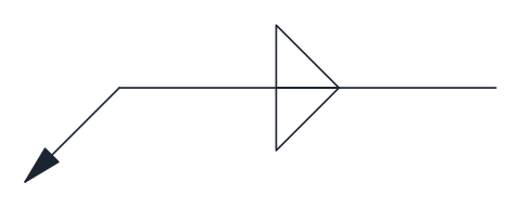
Fillet weld, both sides
Complete welding symbol with fillet triangles on both sides of the reference line and no dashed line, as used for symmetrical welds. Separate attributes take the size and length for each side.
IND_WELDING_SYMBOLS_FILLET_BOTH_SIDES
-
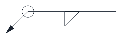
Fillet weld all around
Arrow-side fillet weld with the all-around circle at the junction, for a fillet that runs around the full perimeter of the part.
IND_WELDING_SYMBOLS_FILLET_ALL_AROUND
-
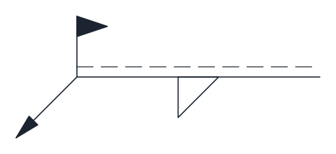
Fillet weld made on site
Arrow-side fillet weld with the field weld flag at the junction, for a fillet weld made during erection rather than in the shop.
IND_WELDING_SYMBOLS_FILLET_FIELD_WELD
-
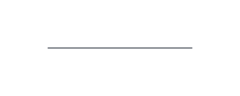
Flush (flat) finish
A straight line added to the weld symbol to ask for a flat weld face, usually dressed flush by grinding or machining.
IND_WELDING_SYMBOLS_FLUSH
-
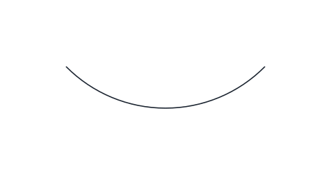
Convex weld face
An arc bulging away from the reference line, added to the weld symbol to ask for a convex weld profile.
IND_WELDING_SYMBOLS_CONVEX
-
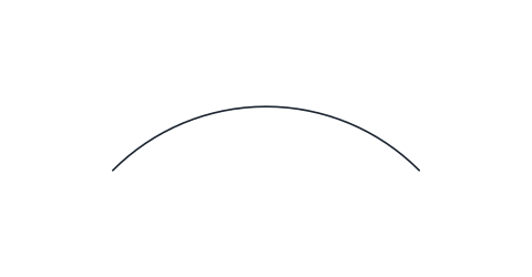
Concave weld face
An arc curving towards the reference line, added to the weld symbol to ask for a concave weld profile, most often on fillet welds.
IND_WELDING_SYMBOLS_CONCAVE
- Units
- Millimetres (INSUNITS 4), drawn at paper size
- Formats
- DWG 2010 · DXF R2010 · PDF
- Opens in
- AutoCAD and AutoCAD LT 2010 or later, BricsCAD, ZWCAD and DraftSight. The DXF opens in most CAD programs.
- Views
- Sheet
- License
- Free for personal and commercial projects. License
This download holds ten fillet weld symbol blocks drawn to ISO 2553: the plain triangle, the double fillet, callouts for the arrow side, the other side and both sides, a fillet all around, a fillet made on site, and the flush, convex and concave contour marks. You get one DWG, one DXF and a PDF sheet, and each block keeps its name from the full welding library, such as IND_WELDING_SYMBOLS_FILLET.
What the fillet weld symbol tells the welder
The triangle stands for the section of a weld laid in the corner between two surfaces, in a T joint, a lap joint or a corner joint. It never turns with the joint: the vertical leg stays on the left whichever way the parts face. The reading rules for arrow, reference line and tail are on the welding symbols page.
Fillet weld size: the a and z dimensions
ISO 2553 puts the size to the left of the symbol with a letter in front. a is the throat thickness, the height of the largest triangle inside the weld section. z is the leg length, measured along each face of the joint. On an equal-leg fillet the leg is the throat times the square root of two, so a5 and z7 describe almost the same weld, while a7 is a much larger one. A bare number with no letter is the US habit, so on an ISO drawing ask the designer.
The length goes to the right of the triangle. With nothing there, the weld runs the full length of the joint. An intermittent fillet is written as the number of segments times their length, with the spacing in brackets.
Double fillet weld symbol and one-sided callouts
When both sides of a T joint get a fillet, the double fillet puts one triangle above and one below the reference line. The weld is symmetrical, so the dashed identification line of system A is left out. The library has it as a bare symbol and as a callout with two pairs of attributes: SIZE and LENGTH for the arrow side, SIZE_OTHER and LENGTH_OTHER for the other side, so unequal fillets can still be described. The one-sided callouts carry a single triangle, on the continuous line or on the dashed line.
Fillet weld contour: flush, convex and concave
A straight line asks for a flat face, an arc bulging away from the reference line for a convex face and an arc curving towards it for a concave one, the profile most often asked for on fillets. For a fillet that runs around a whole tube or bracket, see the weld all around symbol.
Placing fillet weld blocks in AutoCAD
The triangle and the contour marks are 5 mm high and the double fillet 10 mm, on a 2.5 mm grid. The base point of the triangle is the foot of its vertical leg on the reference line. The callouts are placed by the arrow tip, with a 30 mm reference line and a 45 degree arrow. AutoCAD asks for size and length on insert, and an empty attribute prints nothing.
The shapes are drawn after ISO 2553:2019. Its text is sold by ISO and its national member bodies, and none of it is copied on this page.