Instrumentation Symbols
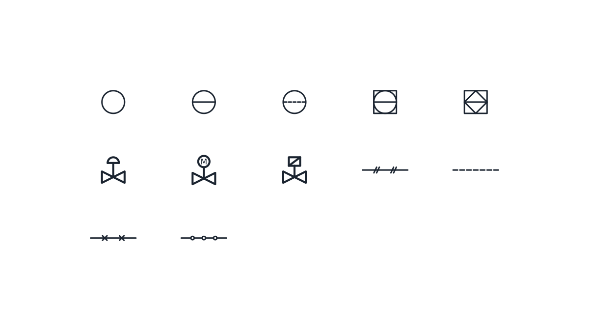
ISA-5.1 instrument bubbles with FUNCTION and LOOP attributes, loop valves and the four signal line types.
Instrumentation symbols library
-

Field-mounted instrument
Plain circle for a discrete instrument mounted in the field, close to the process. Fill in the FUNCTION attribute with the identification letters and LOOP with the loop number.
IND_PID_SYMBOLS_INSTRUMENT_FIELD
-
Panel-mounted instrument
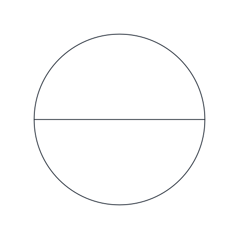
Circle with a solid horizontal line, for a discrete instrument in a primary location such as the control room panel, normally accessible to the operator.
IND_PID_SYMBOLS_INSTRUMENT_PANEL
-
Instrument behind the panel
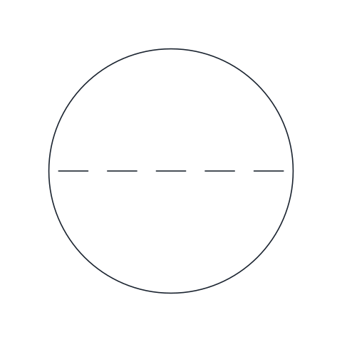
Circle with a dashed horizontal line, for a discrete instrument in a primary location that is not normally accessible to the operator, such as inside a cabinet or behind the panel.
IND_PID_SYMBOLS_INSTRUMENT_BEHIND_PANEL
-
Shared display or control (DCS)
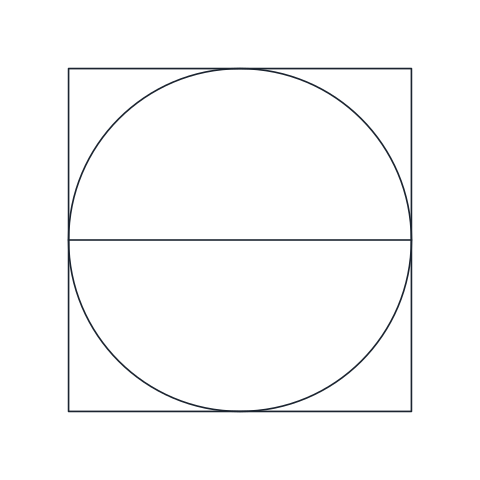
Circle inside a square with a solid horizontal line, for a function shown or controlled on a shared display, typically a DCS operator station in the control room.
IND_PID_SYMBOLS_INSTRUMENT_DCS
-
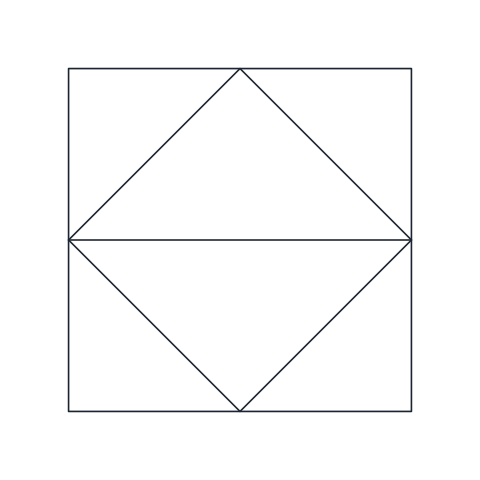
PLC function
Diamond inside a square with a solid horizontal line, for a function performed by a programmable logic controller and accessible to the operator.
IND_PID_SYMBOLS_INSTRUMENT_PLC
-
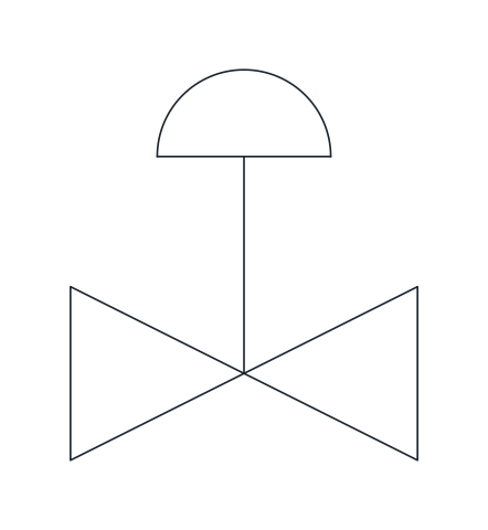
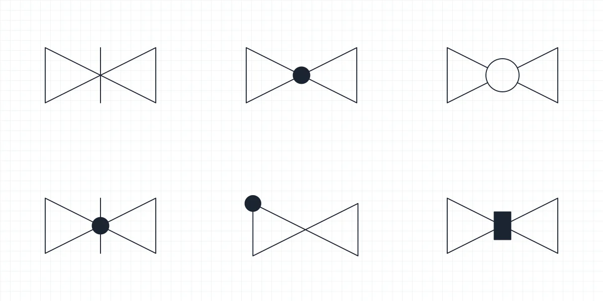
Control valve, diaphragm actuator
Valve body with a stem and a domed spring-and-diaphragm actuator on top. The standard way to show an air-operated modulating control valve in a control loop.
IND_PID_SYMBOLS_CONTROL_VALVE_PNEUMATIC
-
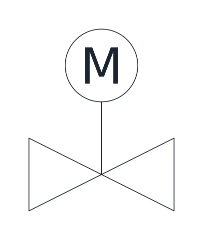
Control valve, electric motor actuator
Valve body with a stem and a circle marked M for an electric motor actuator. Used for motor-operated valves, whether on/off or modulating.
IND_PID_SYMBOLS_CONTROL_VALVE_MOTOR
-
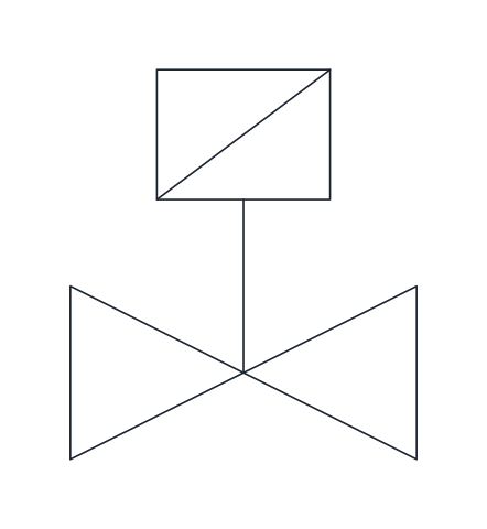
Solenoid valve
Valve body with a stem and a rectangle crossed by a diagonal, the electromagnetic actuator. Shows an electrically switched on/off valve, often on pilot air or small process lines.
IND_PID_SYMBOLS_SOLENOID_VALVE
-
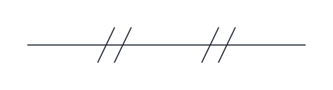
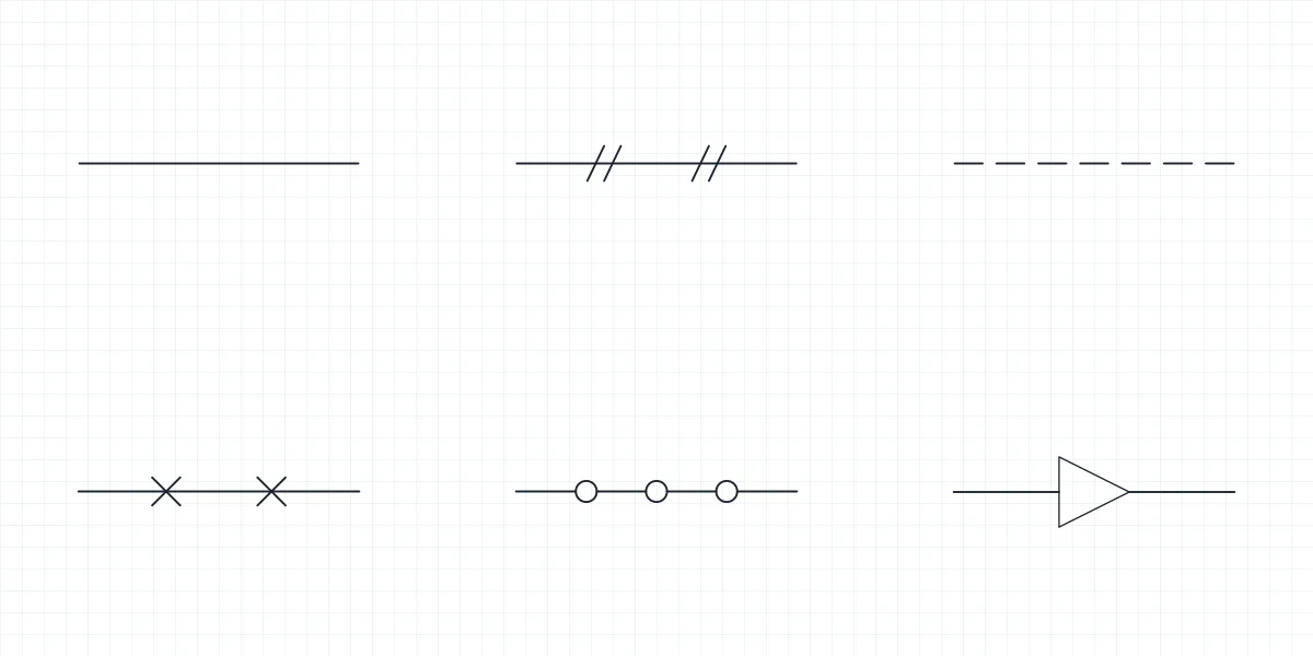
Pneumatic signal line
Thin solid line with pairs of short slashes, for an instrument air signal between a transmitter, controller and actuator.
IND_PID_SYMBOLS_LINE_PNEUMATIC_SIGNAL
-

Electrical signal line
Dashed line for an electrical or electronic signal, such as a 4-20 mA loop between a field transmitter and the control system.
IND_PID_SYMBOLS_LINE_ELECTRICAL_SIGNAL
-
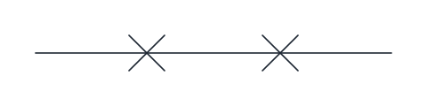
Capillary tube
Thin line with small crosses, for a filled capillary system linking a sensing bulb or remote seal to its instrument.
IND_PID_SYMBOLS_LINE_CAPILLARY
-
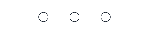
Data link
Thin line interrupted by small circles, for a communication or software link between systems, such as a fieldbus or a link between a PLC and the DCS.
IND_PID_SYMBOLS_LINE_DATA_LINK
- Units
- Millimetres (INSUNITS 4), drawn at paper size
- Formats
- DWG 2010 · DXF R2010 · PDF
- Opens in
- AutoCAD and AutoCAD LT 2010 or later, BricsCAD, ZWCAD and DraftSight. The DXF opens in most CAD programs.
- Views
- Sheet
- License
- Free for personal and commercial projects. License
This download contains 12 instrumentation symbols for P&IDs as named blocks in DWG and DXF, with a PDF legend: five ISA instrument bubbles (field, panel, behind the panel, shared display and PLC), the three actuated valves that close a control loop (diaphragm control valve, motor-operated valve and solenoid valve) and four signal lines (pneumatic, electrical, capillary and data link). The bubbles carry FUNCTION and LOOP attributes, and all block names match the full library, such as IND_PID_SYMBOLS_INSTRUMENT_FIELD.
ISA instrument bubble symbols and their location
The bubble is a 10 mm circle, or a 10 mm square for system functions, placed by its centre. The line inside says where the operator finds the instrument. No line means a discrete instrument in the field. A solid line means a primary location, such as the control room panel, that the operator can normally reach, and a dashed line means the same location but out of normal reach, inside a cabinet or behind the panel. A circle inside a square is a function on a shared display, typically a DCS screen, and a diamond inside a square is a PLC function.
Instrument tag letters and loop numbers
The tag inside the bubble follows ISA-5.1. The first letter is the measured variable: F flow, L level, P pressure, T temperature. The next letters give the function: I indicate, T transmit, C control, A alarm, V valve. So PI is a pressure indicator, TT a temperature transmitter, LIC a level indicating controller and FV the control valve of a flow loop. A modifier can follow the first letter, as D in PDT for a differential pressure transmitter. The loop number goes on the second line and joins every device of the same loop: FT, FIC and FV of one flow loop share it.
Instrument symbols with attributes in AutoCAD
Each bubble has two attributes, FUNCTION 2 mm above the centre and LOOP 2 mm below, both 2.5 mm high, centred and empty by default, on layer G-ANNO-TEXT. AutoCAD asks for both values on insert. Change them later by double-clicking the block, and when the drawing is done, DATAEXTRACTION in full AutoCAD (not LT) can list every tag to start an instrument index. The dashed line of the behind-the-panel bubble is drawn as separate segments, so it does not depend on LTSCALE.
Signal lines in instrumentation diagrams
Each line sample is 20 mm long, with its base point on the left end. The pneumatic signal is a thin line with pairs of short slashes, the capillary tube has small crosses and the data link is broken by small circles. The electrical signal is a dashed line on layer D-PID-SIGN using the DASHED_S linetype, a 2 mm dash and 1 mm gap, so check LTSCALE if the dashes look wrong at your plot scale. ISA-5.1 has changed the communication lines between editions, so check the data link against the edition your client names.
A loop needs a valve at the end, described on the valve symbols page, and process lines to connect it, on the piping symbols page. The bubbles together with all equipment are in the P&ID symbols library.
Bubbles, tags and signal lines are drawn after ISA-5.1, a standard that the International Society of Automation sells. We describe its conventions in our own words and do not reproduce it.