Heat Exchanger Symbol
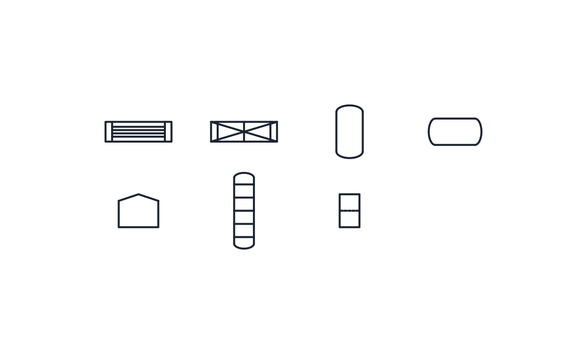
Shell and tube and plate exchangers with the vessels, tank, column and filter that sit beside them on a P&ID.
Heat exchanger symbol library
-
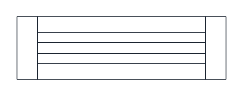
Shell and tube heat exchanger
Long rectangle with a tube sheet near each end and a bundle of straight tubes between them. Represents a fixed tube-sheet exchanger; connect the shell-side and tube-side lines to the matching faces.
IND_PID_SYMBOLS_SHELL_TUBE_HEAT_EXCHANGER
-
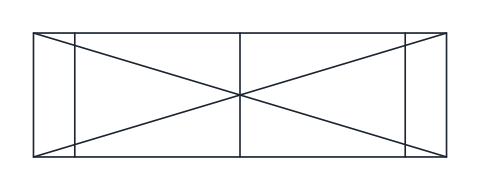
Plate heat exchanger
Rectangle with three cross bars and a full diagonal cross, for gasketed or brazed plate exchangers that pass two fluids through alternate channels.
IND_PID_SYMBOLS_PLATE_HEAT_EXCHANGER
-
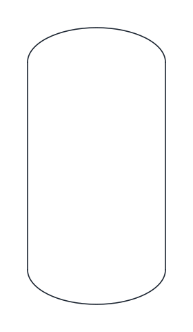
Vertical vessel
Upright cylindrical vessel with dished heads at both ends. Use it for drums, receivers, separators and reactors standing on end.
IND_PID_SYMBOLS_VERTICAL_VESSEL
-
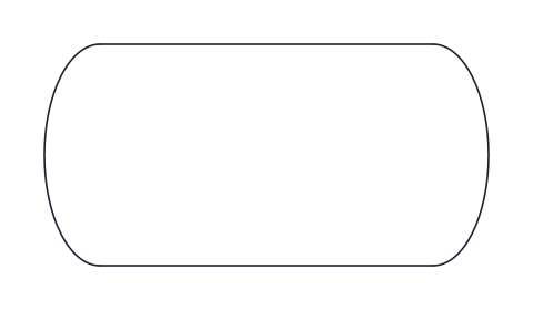
Horizontal vessel
Cylindrical vessel lying on its side with dished heads, for accumulators, storage drums and horizontal separators.
IND_PID_SYMBOLS_HORIZONTAL_VESSEL
-
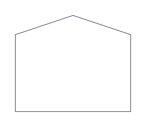
Atmospheric storage tank
Flat-bottomed tank with a low conical roof, the usual picture of a storage tank working at or near atmospheric pressure.
IND_PID_SYMBOLS_ATMOSPHERIC_TANK
-
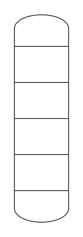
Tray column
Tall vessel with dished heads and horizontal lines for trays, used for distillation, absorption and stripping columns. Remove or add tray lines to match the drawing scale.
IND_PID_SYMBOLS_COLUMN
-
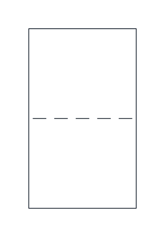
Liquid filter
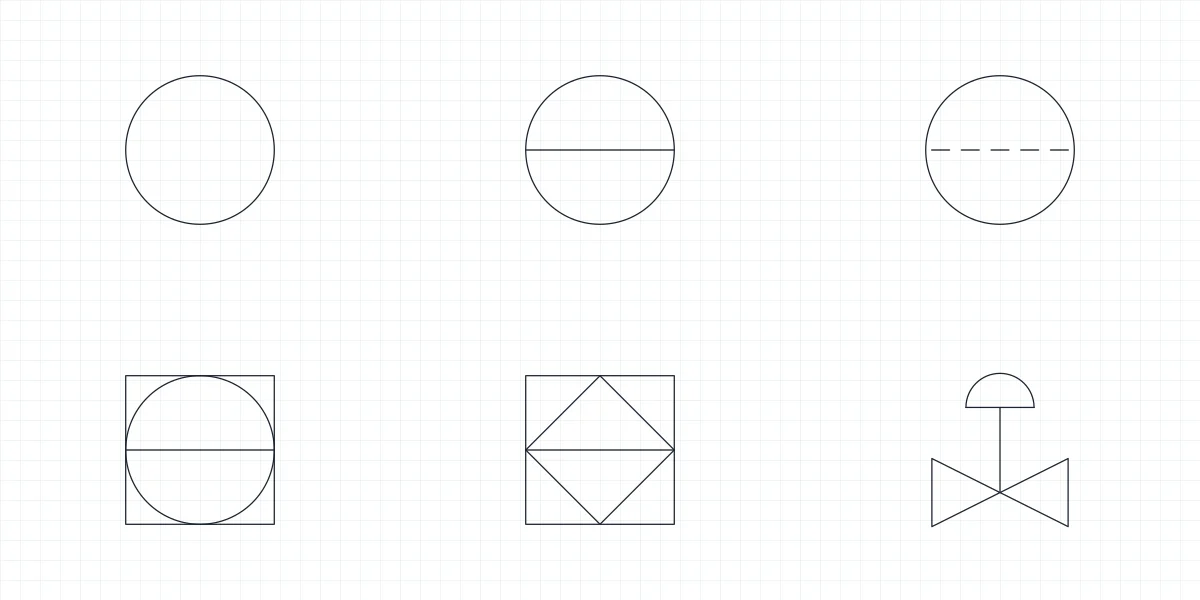
Upright housing with a dashed line across it for the filter element. Use it for in-line liquid filters and cartridge housings when the filter type need not be detailed.
IND_PID_SYMBOLS_FILTER
- Units
- Millimetres (INSUNITS 4), drawn at paper size
- Formats
- DWG 2010 · DXF R2010 · PDF
- Opens in
- AutoCAD and AutoCAD LT 2010 or later, BricsCAD, ZWCAD and DraftSight. The DXF opens in most CAD programs.
- Views
- Sheet
- License
- Free for personal and commercial projects. License
This download holds the heat exchanger symbol in its shell and tube and plate forms, together with the vessel symbols that usually stand beside it on a P&ID: vertical vessel, horizontal vessel, atmospheric storage tank, tray column and liquid filter. That makes 7 named blocks in DWG and DXF and a PDF sheet. Each keeps the name it has in the full library, such as IND_PID_SYMBOLS_SHELL_TUBE_HEAT_EXCHANGER, so it is the same block in both downloads.
Shell and tube heat exchanger symbol
The block is a long rectangle, 25 by 7.5 mm, with a tube sheet near each end and a bundle of straight tubes running between them. That is the fixed tube-sheet exchanger. When you connect it, take the tube-side lines to the ends, beyond the tube sheets where the channels are, and the shell-side lines to the long faces between the tube sheets. Label the two sides on the drawing if the fluids are not obvious from the lines, since the symbol itself does not say which fluid is hot.
Plate heat exchanger symbol
The plate exchanger uses the same 25 by 7.5 mm envelope, with three cross bars and a full diagonal cross from corner to corner. It stands for gasketed or brazed plate units, where the two fluids pass through alternate channels between the plates. Because both exchanger blocks share their size and their base point at the centre, you can swap one for the other without moving any line. U-tube, kettle and air-cooled exchangers are not part of this set.
Vessel symbols that go with the exchanger
The vertical vessel, 10 by 20 mm, has dished heads at both ends and serves for drums, receivers, separators and reactors. The horizontal vessel is the same shape on its side, 20 by 10 mm, for storage drums and horizontal separators. The heads are drawn as 2:1 ellipses. The atmospheric storage tank, 15 by 12.5 mm, has a flat bottom and a low conical roof. The tray column is 7.5 by 28.75 mm with its trays drawn as plain lines, so add or delete trays to suit your scale. The liquid filter is an upright housing with a dashed line for the element.
Placing heat exchanger and vessel blocks
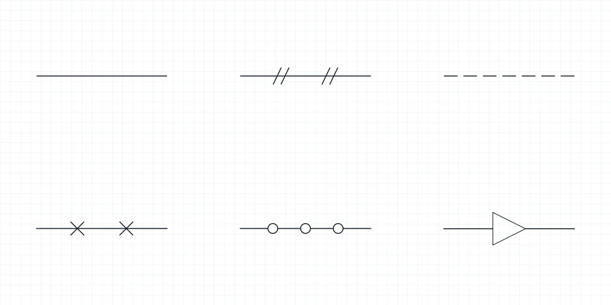
All seven blocks are placed by their centre. A P&ID is not drawn to scale, so you can give a vessel a different X and Y scale on insert to make room for nozzles and instruments; the centre stays where you put it. The dashed line inside the filter is drawn as separate segments, so it looks the same whatever LTSCALE the drawing uses. Pumps and the agitator that sits on a vessel head are on the pump symbol page, the line types and flanges that link it all are on the piping symbols page, and the full set is the P&ID symbols library.
Equipment shapes follow ISO 10628-2. That standard is on sale from ISO and from national standards bodies; what you download here is our own drawing of its conventions, and an operator's legend sheet overrides it when there is one.