Valve Symbols
Fifteen P&ID valve symbols on one body size, from the gate valve to control valves with their actuators.
Valve symbols library
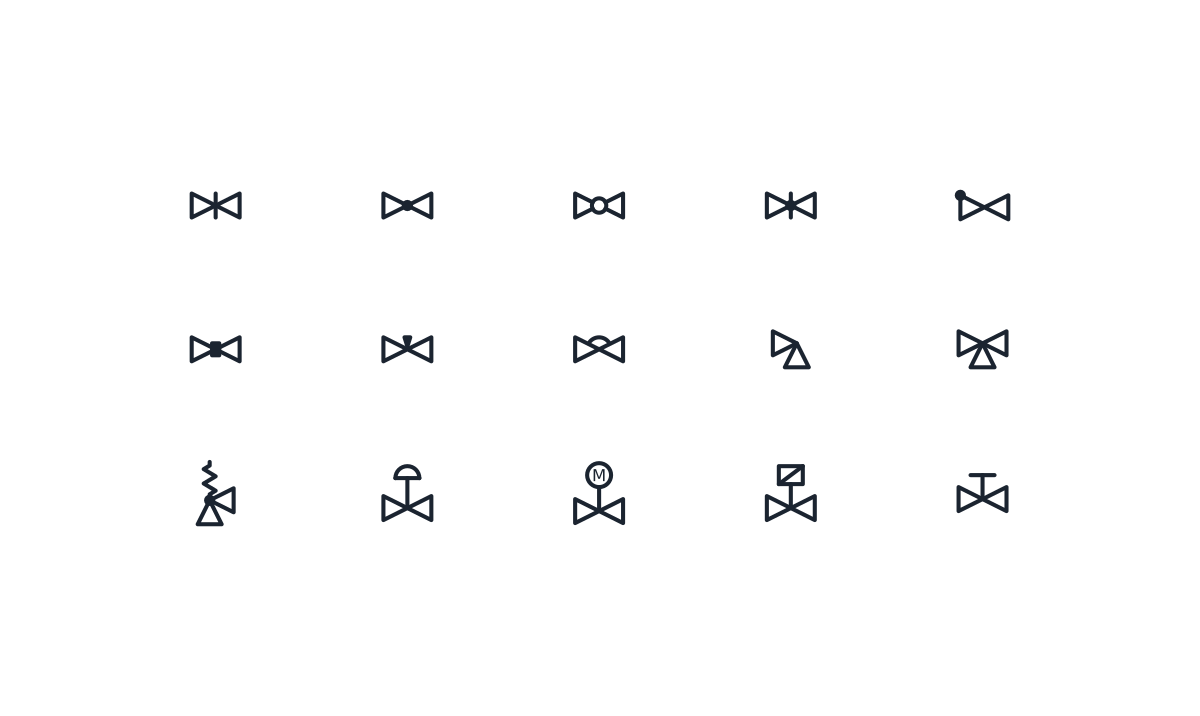
-
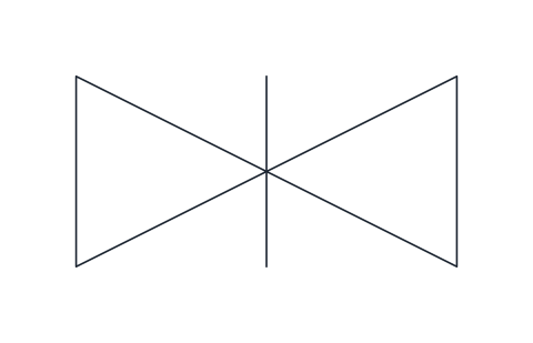
Gate valve
Two opposed triangles with a vertical bar through the centre for an on/off isolating valve whose gate slides across the flow. Use it for block valves that stay fully open or fully closed.
IND_PID_SYMBOLS_GATE_VALVE
-
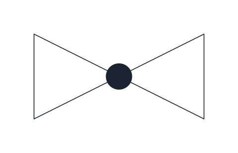
Globe valve
Valve body with a solid dot at the centre, marking a globe-pattern seat. Typical for throttling duties and bypasses where flow is adjusted by hand.
IND_PID_SYMBOLS_GLOBE_VALVE
-
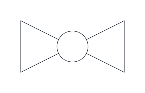
Ball valve
Valve body with an open circle at the centre for a quarter-turn valve with a bored ball. Common on utility lines and tight shut-off services.
IND_PID_SYMBOLS_BALL_VALVE
-
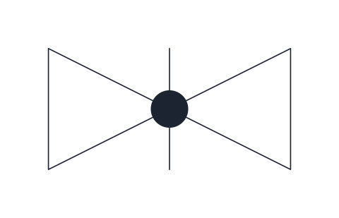
Butterfly valve
Valve body with a vertical bar and a centre dot representing the disc on its spindle. Used on large-bore lines for isolation or coarse throttling.
IND_PID_SYMBOLS_BUTTERFLY_VALVE
-
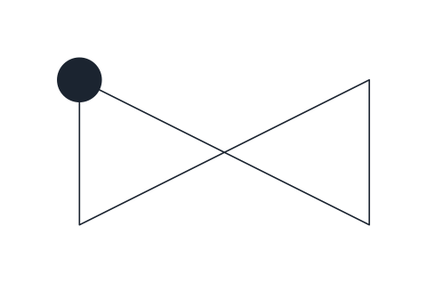
Check valve
Valve body with a solid dot on the inlet corner, the general non-return valve. Draw it with the inlet on the left so the permitted flow runs left to right.
IND_PID_SYMBOLS_CHECK_VALVE
-
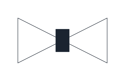
Plug valve
Valve body with a solid rectangle at the centre standing for the rotating plug. Used for quarter-turn isolation on slurries, gas and viscous fluids.
IND_PID_SYMBOLS_PLUG_VALVE
-
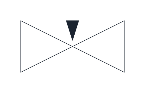
Needle valve
Valve body with a small solid wedge pointing into the seat, for fine flow adjustment on instrument connections, sampling points and small bleed lines.
IND_PID_SYMBOLS_NEEDLE_VALVE
-
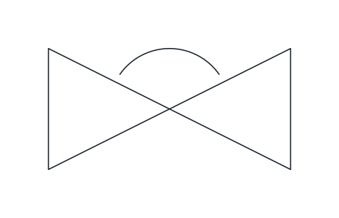
Diaphragm valve
Valve body with an arc over the centre representing the flexible diaphragm that closes onto a weir. Chosen for corrosive, abrasive or hygienic services.
IND_PID_SYMBOLS_DIAPHRAGM_VALVE
-
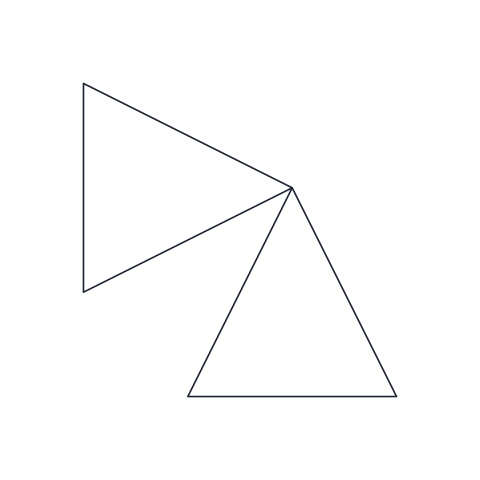
Angle valve
Two triangles at right angles: the flow enters from the left and leaves downward, or the reverse. Use it where the valve also turns the line through 90 degrees.
IND_PID_SYMBOLS_ANGLE_VALVE
-
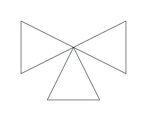
Three-way valve
In-line valve body with a third port pointing down, for diverting one stream into two or mixing two streams into one.
IND_PID_SYMBOLS_THREE_WAY_VALVE
-
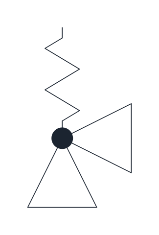
Safety relief valve
Angle valve with a spring above it: the inlet comes from the protected equipment below and the discharge leaves to the side. Marks a pressure relief device set to open on overpressure.
IND_PID_SYMBOLS_SAFETY_RELIEF_VALVE
-
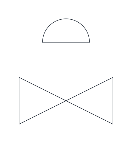
Control valve, diaphragm actuator
Valve body with a stem and a domed spring-and-diaphragm actuator on top. The standard way to show an air-operated modulating control valve in a control loop.
IND_PID_SYMBOLS_CONTROL_VALVE_PNEUMATIC
-
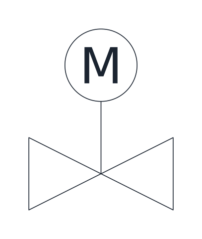
Control valve, electric motor actuator
Valve body with a stem and a circle marked M for an electric motor actuator. Used for motor-operated valves, whether on/off or modulating.
IND_PID_SYMBOLS_CONTROL_VALVE_MOTOR
-
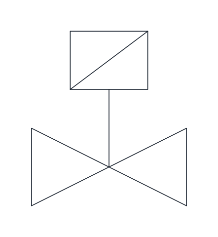
Solenoid valve
Valve body with a stem and a rectangle crossed by a diagonal, the electromagnetic actuator. Shows an electrically switched on/off valve, often on pilot air or small process lines.
IND_PID_SYMBOLS_SOLENOID_VALVE
-
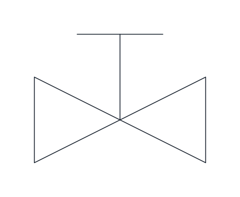
Hand-operated valve
Valve body with a stem ending in a T-bar for a handwheel. Use it where the drawing needs to state explicitly that the valve is operated by hand.
IND_PID_SYMBOLS_MANUAL_VALVE_HANDWHEEL
- Units
- Millimetres (INSUNITS 4), drawn at paper size
- Formats
- DWG 2010 · DXF R2010 · PDF
- Opens in
- AutoCAD and AutoCAD LT 2010 or later, BricsCAD, ZWCAD and DraftSight. The DXF opens in most CAD programs.
- Views
- Sheet
- License
- Free for personal and commercial projects. License
This download holds the 15 P&ID valve symbols of the library as named blocks in DWG and DXF, with a PDF legend: gate, globe, ball, butterfly, check, plug, needle, diaphragm, angle, three-way and safety relief valves, two control valves, a solenoid valve and a hand-operated valve. Block names match the full library, such as IND_PID_SYMBOLS_GATE_VALVE.
Isolation valve symbols: gate, ball, butterfly and plug
Every in-line valve starts from a body of two triangles meeting at their points, 10 mm long and 5 mm high, and a mark at the centre tells the type. The gate valve carries a vertical bar. Two triangles on their own read as a general valve in ISO 10628-2, while some legends use them for a gate valve, so the bar removes the doubt. The ball valve has an open circle, the butterfly valve a bar with a dot for the disc on its spindle, and the plug valve a solid rectangle for the rotating plug.
Throttling valve symbols: globe, needle and diaphragm
A solid dot at the centre marks the globe valve, the usual choice for throttling and bypass lines. The needle valve has a small solid wedge pointing into the seat and belongs on instrument connections, sample points and small bleeds. The diaphragm valve shows an arc over the body for the flexible diaphragm, and it is picked for corrosive, abrasive or hygienic services. The check valve has a page of its own: check valve symbols.
Angle, three-way and safety relief valve symbols
The angle valve turns its second triangle to point down instead of right, and the three-way valve adds a third one pointing down. In both, the lower port sits 5 mm right of the base point and 5 mm below it. The three-way valve diverts one stream into two or mixes two into one. The safety relief valve is an angle valve with a spring: the inlet comes up from the protected equipment to the base point, the body centre is 5 mm above it and the discharge leaves to the right.
Control valve symbol and other actuated valves
Actuated valves carry the actuator on a stem above the centre of the body. A dome is the spring-and-diaphragm actuator of an air-operated control valve, a circle with an M is an electric motor actuator, and a rectangle crossed by a diagonal is the electromagnetic actuator of a solenoid valve. Many American P&IDs draw the solenoid as a square with an S instead, so follow the legend of the job. A T-bar at the top of the stem states that the valve is worked by hand.
A control valve is the last element of a loop, so it normally takes a tag such as FV or LV and a signal line from its controller. The bubbles and lines are on the instrumentation symbols page, and the full set of equipment and lines is in the P&ID symbols library. In-line valves have their base point on the left connection and the right one 10 mm along, on the 2.5 mm grid.
Valve forms follow ISO 10628-2 and the actuated valves also follow ISA-5.1. Both documents are sold by their publishers, and this page only describes our own drawings of them.