Electrical Schematic Symbols
41 schematic symbols for control circuits and machine wiring, drawn after IEC 60617 with contacts in their rest position.
Electrical Schematic Symbols library
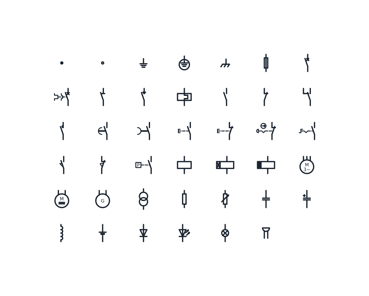
Connection and earth symbols
-

Conductor junction
A filled dot marking a point where conductors are electrically joined. Place it wherever a branch leaves a line so a crossing is never mistaken for a connection.
IND_ELECTRICAL_SCHEMATIC_SYMBOLS_CONDUCTOR_JUNCTION
-

Terminal
An open circle for a connection point on a device or terminal strip, where an external conductor is clamped or screwed.
IND_ELECTRICAL_SCHEMATIC_SYMBOLS_TERMINAL
-
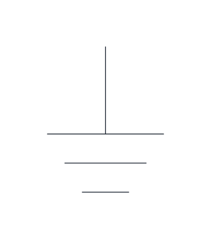
Earth (ground)
The general earth connection: a lead ending in three lines of decreasing length. Use it when the earthing has no specific protective or functional role to show.
IND_ELECTRICAL_SCHEMATIC_SYMBOLS_EARTH
-
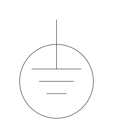
Protective earth (PE)
Earth symbol enclosed in a circle, used for the protective earth conductor that keeps exposed metal parts at earth potential in case of an insulation fault.
IND_ELECTRICAL_SCHEMATIC_SYMBOLS_PROTECTIVE_EARTH
-
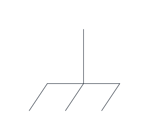
Chassis or frame connection
A line with diagonal hatching that shows a connection to the metal frame or enclosure of the equipment rather than to a true earth.
IND_ELECTRICAL_SCHEMATIC_SYMBOLS_CHASSIS_FRAME
Protection and switching symbols
-
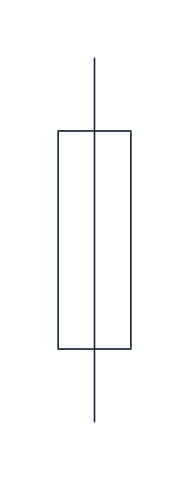
Fuse
A narrow rectangle with the conductor running through it, for a fuse link that melts and opens the circuit on overcurrent.
IND_ELECTRICAL_SCHEMATIC_SYMBOLS_FUSE
-
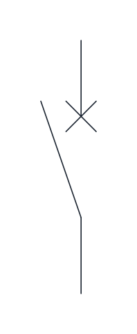
Circuit breaker
A make contact with a cross at the fixed contact, showing a device that can make, carry and break normal and fault currents, such as a miniature circuit breaker.
IND_ELECTRICAL_SCHEMATIC_SYMBOLS_CIRCUIT_BREAKER
-
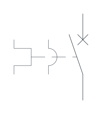
Motor protective circuit breaker
Circuit breaker contact linked to a magnetic release and a thermal release, the usual single-pole representation of a motor protection switch that trips on short circuit and on overload.
IND_ELECTRICAL_SCHEMATIC_SYMBOLS_MOTOR_PROTECTIVE_CIRCUIT_BREAKER
-
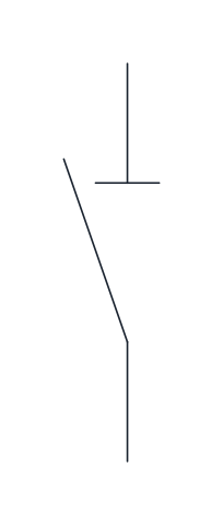
Disconnector (isolator)
A make contact with a short bar across the fixed contact. It provides a visible isolating gap and is operated off load, before maintenance work.
IND_ELECTRICAL_SCHEMATIC_SYMBOLS_DISCONNECTOR
-
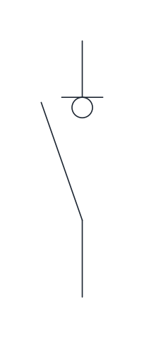
Switch-disconnector
A contact carrying both the isolating bar and the small circle of the switching function, for a main switch that can open under load and also isolate the circuit.
IND_ELECTRICAL_SCHEMATIC_SYMBOLS_SWITCH_DISCONNECTOR
-
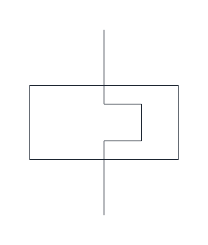
Thermal overload relay
The heating element of a thermal overload relay, drawn in the power circuit between the contactor and the motor. Its auxiliary contacts appear separately in the control circuit.
IND_ELECTRICAL_SCHEMATIC_SYMBOLS_THERMAL_OVERLOAD_RELAY
Contact symbols
-
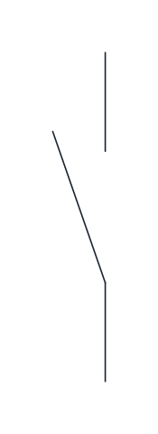
Normally open contact
A make contact, open at rest and closed when the device that drives it is actuated. It is the basic element for start commands and holding circuits.
IND_ELECTRICAL_SCHEMATIC_SYMBOLS_NO_CONTACT
-
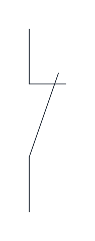
Normally closed contact
A break contact, closed at rest and opened on actuation. The blade crosses the hook of the fixed contact to show that it is touching.
IND_ELECTRICAL_SCHEMATIC_SYMBOLS_NC_CONTACT
-
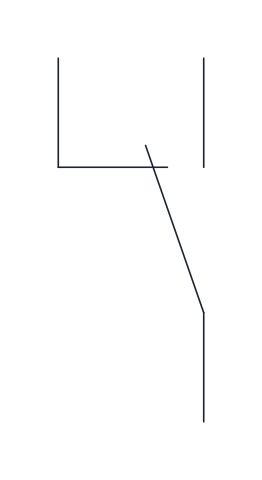
Changeover contact
One moving blade shared by a break contact and a make contact, opening one before closing the other. Common on relays that switch between two circuits.
IND_ELECTRICAL_SCHEMATIC_SYMBOLS_CHANGEOVER_CONTACT
-
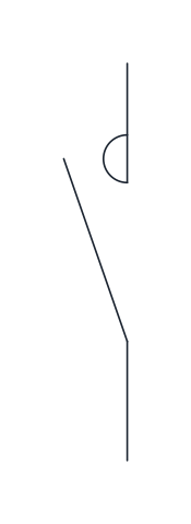
Contactor main contact
A make contact with a semicircle at the fixed contact, marking a main power contact of a contactor rated to switch motor or load currents.
IND_ELECTRICAL_SCHEMATIC_SYMBOLS_CONTACTOR_MAIN_CONTACT_NO
-
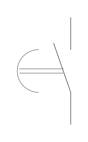
On-delay make contact
A make contact that closes after a set delay once the timer is energized and opens without delay when it is de-energized.
IND_ELECTRICAL_SCHEMATIC_SYMBOLS_TIME_DELAY_ON_NO_CONTACT
-
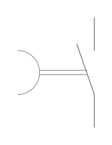
Off-delay make contact
A make contact that closes at once when the timer is energized and opens only after a set delay once it is de-energized.
IND_ELECTRICAL_SCHEMATIC_SYMBOLS_TIME_DELAY_OFF_NO_CONTACT
Push button and switch symbols
-
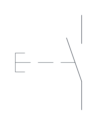
Pushbutton, normally open
A make contact operated by pushing, with automatic return. The typical start button of a control circuit.
IND_ELECTRICAL_SCHEMATIC_SYMBOLS_PUSHBUTTON_NO
-
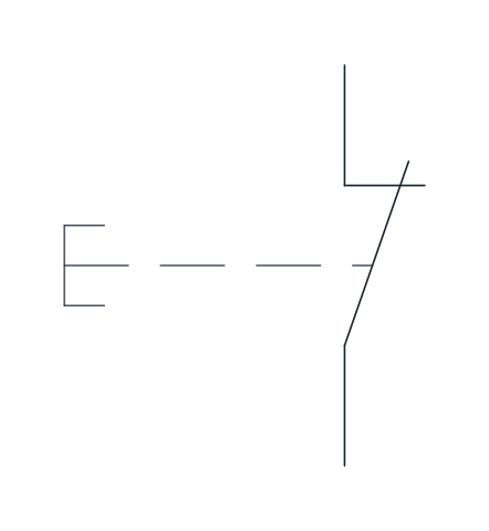
Pushbutton, normally closed
A break contact operated by pushing, with automatic return, used for stop buttons wired in series with the holding circuit.
IND_ELECTRICAL_SCHEMATIC_SYMBOLS_PUSHBUTTON_NC
-
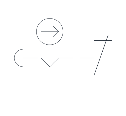
Emergency stop (mushroom head)
A break contact with a mushroom-head actuator, a latching notch and the positive opening mark. It stays latched once pressed and has to be reset by hand.
IND_ELECTRICAL_SCHEMATIC_SYMBOLS_EMERGENCY_STOP_MUSHROOM
-
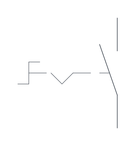
Selector switch
A make contact operated by turning, with a detent that holds the selected position, for mode choices such as manual and automatic.
IND_ELECTRICAL_SCHEMATIC_SYMBOLS_SELECTOR_SWITCH
-
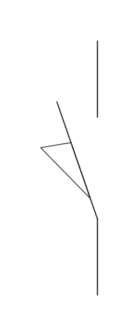
Limit switch, normally open
A position switch whose make contact closes when a moving part of the machine reaches it. The wedge on the blade marks mechanical actuation by position.
IND_ELECTRICAL_SCHEMATIC_SYMBOLS_LIMIT_SWITCH_NO
-
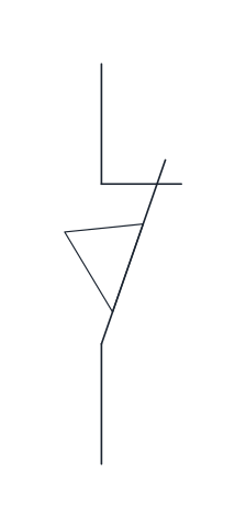
Limit switch, normally closed
A position switch whose break contact opens when the moving part reaches the end of its travel, often used to stop a drive.
IND_ELECTRICAL_SCHEMATIC_SYMBOLS_LIMIT_SWITCH_NC
-
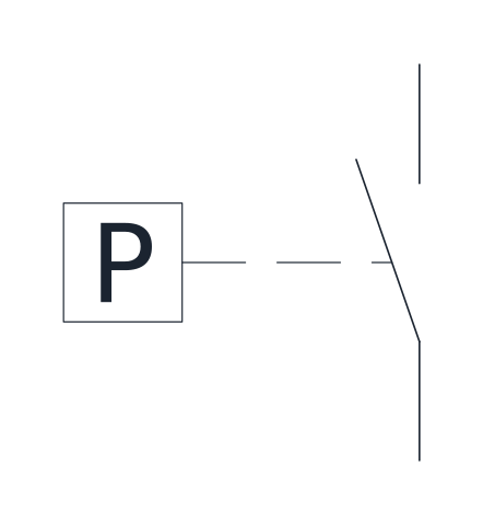
Pressure switch, normally open
A make contact operated by the pressure of a liquid or gas, which closes when the set pressure is reached. Used on compressors, pumps and hydraulic units.
IND_ELECTRICAL_SCHEMATIC_SYMBOLS_PRESSURE_SWITCH_NO
Relay and contactor coil symbols
-
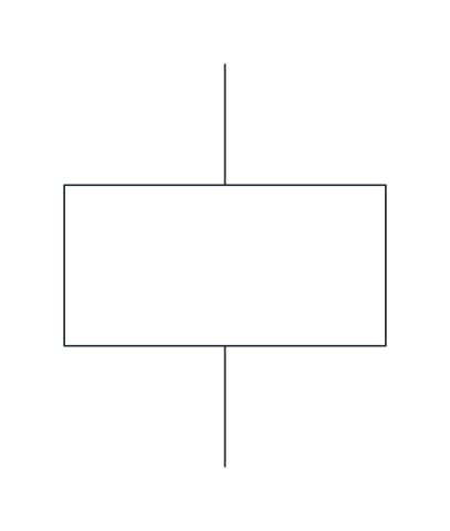
Relay or contactor coil
A rectangle for the operating coil of a relay or contactor. Its contacts are drawn elsewhere and share its reference designation.
IND_ELECTRICAL_SCHEMATIC_SYMBOLS_COIL
-
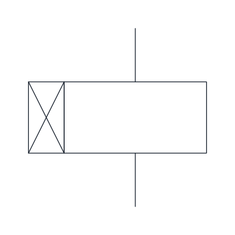
Coil, on-delay timer
Coil of a slow-operating relay, marked with a crossed box. Its contacts change state a set time after the coil is energized.
IND_ELECTRICAL_SCHEMATIC_SYMBOLS_COIL_TIME_DELAY_ON
-

Coil, off-delay timer
Coil of a slow-releasing relay, marked with a filled box. Its contacts return to rest a set time after the coil is de-energized.
IND_ELECTRICAL_SCHEMATIC_SYMBOLS_COIL_TIME_DELAY_OFF
Motor and transformer symbols
-
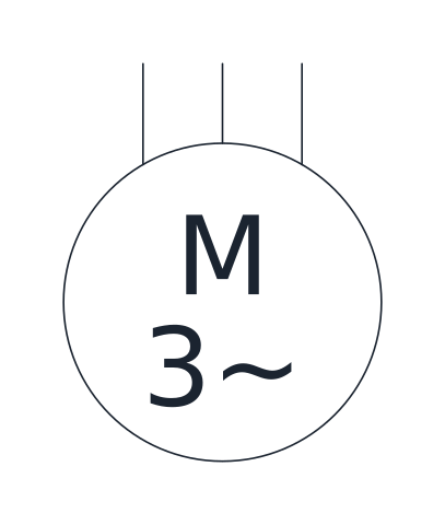
Three-phase motor
A circle with M and 3~ and three supply leads, for an AC three-phase motor such as a squirrel-cage induction motor fed from a starter.
IND_ELECTRICAL_SCHEMATIC_SYMBOLS_MOTOR_THREE_PHASE
-
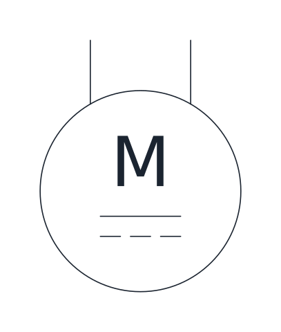
DC motor
A circle with M and the direct current sign, with two supply leads, for a motor fed from a DC source or drive.
IND_ELECTRICAL_SCHEMATIC_SYMBOLS_MOTOR_DC
-
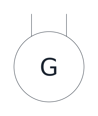
Generator
A circle with G for a rotating generator. Add the current type next to it when the drawing needs it.
IND_ELECTRICAL_SCHEMATIC_SYMBOLS_GENERATOR
-
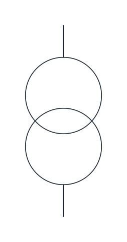
Two-winding transformer
Two overlapping circles for a transformer with separate primary and secondary windings, such as a control-circuit transformer.
IND_ELECTRICAL_SCHEMATIC_SYMBOLS_TRANSFORMER_TWO_WINDING
Electronic component symbols
-
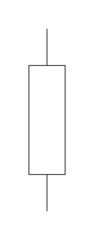
Resistor
A rectangle with a lead at each end for a fixed resistor.
IND_ELECTRICAL_SCHEMATIC_SYMBOLS_RESISTOR
-
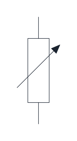
Variable resistor
A resistor crossed by an oblique arrow, showing that its value can be adjusted, as in a rheostat or trimmer.
IND_ELECTRICAL_SCHEMATIC_SYMBOLS_VARIABLE_RESISTOR
-
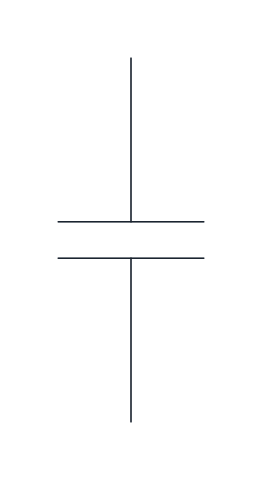
Capacitor
Two parallel plates for a non-polarized capacitor, as used for interference suppression or power factor correction.
IND_ELECTRICAL_SCHEMATIC_SYMBOLS_CAPACITOR
-
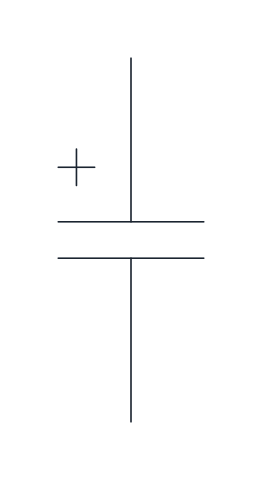
Polarized capacitor
A capacitor with a plus sign at the positive plate, for electrolytic capacitors that must be connected the right way round.
IND_ELECTRICAL_SCHEMATIC_SYMBOLS_POLARISED_CAPACITOR
-
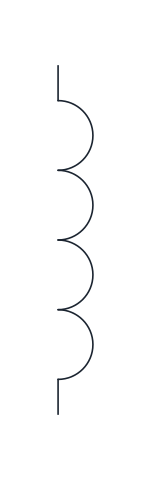
Inductor
A row of four half loops for a coil or choke whose function is its inductance, such as a line reactor.
IND_ELECTRICAL_SCHEMATIC_SYMBOLS_INDUCTOR
-
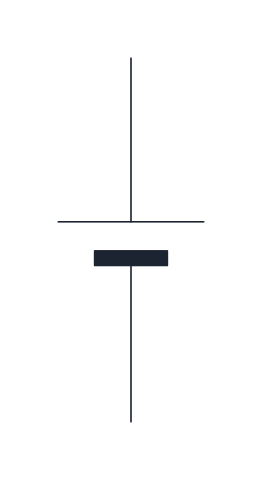
Battery cell
A long thin plate for the positive pole and a short thick plate for the negative pole of a single cell. Repeat it for a multi-cell battery.
IND_ELECTRICAL_SCHEMATIC_SYMBOLS_BATTERY_CELL
-
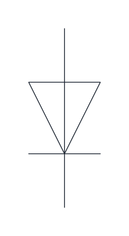
Diode
A triangle and bar showing a semiconductor diode that conducts from anode to cathode, the bar side. Drawn here with the anode at the top.
IND_ELECTRICAL_SCHEMATIC_SYMBOLS_DIODE
-
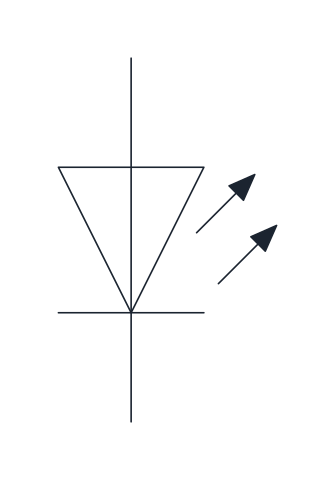
Light-emitting diode (LED)
A diode with two outward arrows that show emitted light, used for indicator LEDs on panels and boards.
IND_ELECTRICAL_SCHEMATIC_SYMBOLS_LED
-
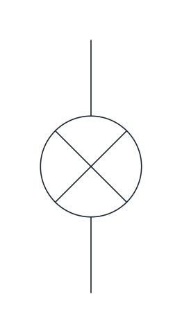
Signal lamp
A circle with a cross for an indicator or pilot lamp that shows a state such as running, fault or power on.
IND_ELECTRICAL_SCHEMATIC_SYMBOLS_SIGNAL_LAMP
-
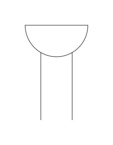
Buzzer
A semicircle with a flat top and two leads for an audible signalling device, often wired to a fault or alarm contact.
IND_ELECTRICAL_SCHEMATIC_SYMBOLS_BUZZER
- Units
- Millimetres (INSUNITS 4), drawn at paper size
- Formats
- DWG 2010 · DXF R2010 · PDF
- Opens in
- AutoCAD and AutoCAD LT 2010 or later, BricsCAD, ZWCAD and DraftSight. The DXF opens in most CAD programs.
- Views
- Sheet
- License
- Free for personal and commercial projects. License
This library draws the electrical schematic symbols used in control panels and machine wiring diagrams, after the conventions of IEC 60617: contacts, coils, protective devices, push buttons, motors and basic components. Every symbol is a named block in the DWG and DXF, and the PDF sheet works as a printable chart of the symbols with their names.
Electrical schematic symbols and wiring diagram symbols
A schematic shows how a circuit works, not where the parts are. That is why the symbols here are the ones of circuit diagrams and wiring diagrams, not the plan symbols of building drawings: you will find a normally open contact and a contactor coil, but not a wall socket or a ceiling light. IEC 60617 is published as a database of more than 1,500 symbols, and this library takes the ones that come up in almost every control circuit.
How contact and coil symbols are drawn
Contacts are always drawn in their rest position, with the device de-energised and nothing pressed. A normally open contact is drawn open and closes when its coil or push button acts on it; a normally closed contact is drawn closed. A changeover contact combines both. The coil of a relay or contactor is a rectangle, and variants mark a delay on operation or on release. When a contact and the device that moves it are drawn apart, a dashed line, the mechanical link, shows that they belong together.
All contacts in the library share the same length and the same distance between terminals, so they line up in a ladder without adjusting.
Symbols for protection, switching and motors
The protection group covers the fuse, the circuit breaker, the motor protective circuit breaker, the thermal overload relay and the disconnector. The control group has push buttons, the mushroom-head emergency stop, selector switches and limit switches. Motors are drawn as a circle with the letter M, and a three-phase motor adds 3~ under it. Passive components, diodes, LEDs, the signal lamp and the buzzer complete the set.
Reference designations next to the symbols
On a schematic each symbol carries a reference designation, and IEC 81346-2 assigns the letter by what the device does. A few classes cover most of a control panel:
- F protecting: fuses, circuit breakers, overload relays
- K processing signals: relays and timers
- M providing mechanical energy: motors
- P presenting information: lamps and buzzers
- Q controlled switching of power: contactors and power switches
- S converting a manual action into a signal: push buttons and selector switches
- X connecting: terminals
The blocks carry no text, so you can add the designation in your own text style and on your own layer.
Using the schematic symbols in your CAD program
The symbols are drawn at paper size on a 2.5 mm grid with the current path vertical. In-line devices have their base point on the lower terminal and the upper terminal 12.5 mm above it, so they snap onto wires drawn on the same grid. Machines, junctions and terminals are placed by their centre. Insert them from DesignCenter (ADCENTER) in AutoCAD, or open the DXF in any CAD program and copy the blocks into your template. The DWG is saved for AutoCAD 2010 and later.
The forms follow IEC 60617, which IEC sells as a subscription database. If a project follows another convention, such as the US practice of drawing contacts with parallel lines, check the symbols your client expects.
Electrical symbol libraries by device
- Relay symbol: coil, contact and timer blocks for CAD: Coils, contacts, timer relays and the contactor main contact as IEC 60617 blocks for control schematics.
- Circuit breaker symbol and fuse blocks for CAD: Protective and isolating device symbols as CAD blocks, with how to tell a breaker, a disconnector and a fuse apart.
- Motor symbol: three phase motor and transformer blocks: Motor, generator and transformer symbols as CAD blocks, with the three devices of a direct-on-line feeder.
- Push button symbol and emergency stop blocks for CAD: Push buttons, the emergency stop, selector and limit switches, a lamp and a buzzer as schematic CAD blocks.
- Capacitor symbol and component blocks for CAD: Capacitors, resistors, an inductor, a battery cell, a diode and an LED as IEC 60617 CAD blocks.
- Ladder diagram symbols: IEC 61131-3 blocks for CAD: The graphic elements of IEC 61131-3 ladder logic as CAD blocks, from contacts and coils to timers and counters.