Push button symbol and emergency stop blocks for CAD
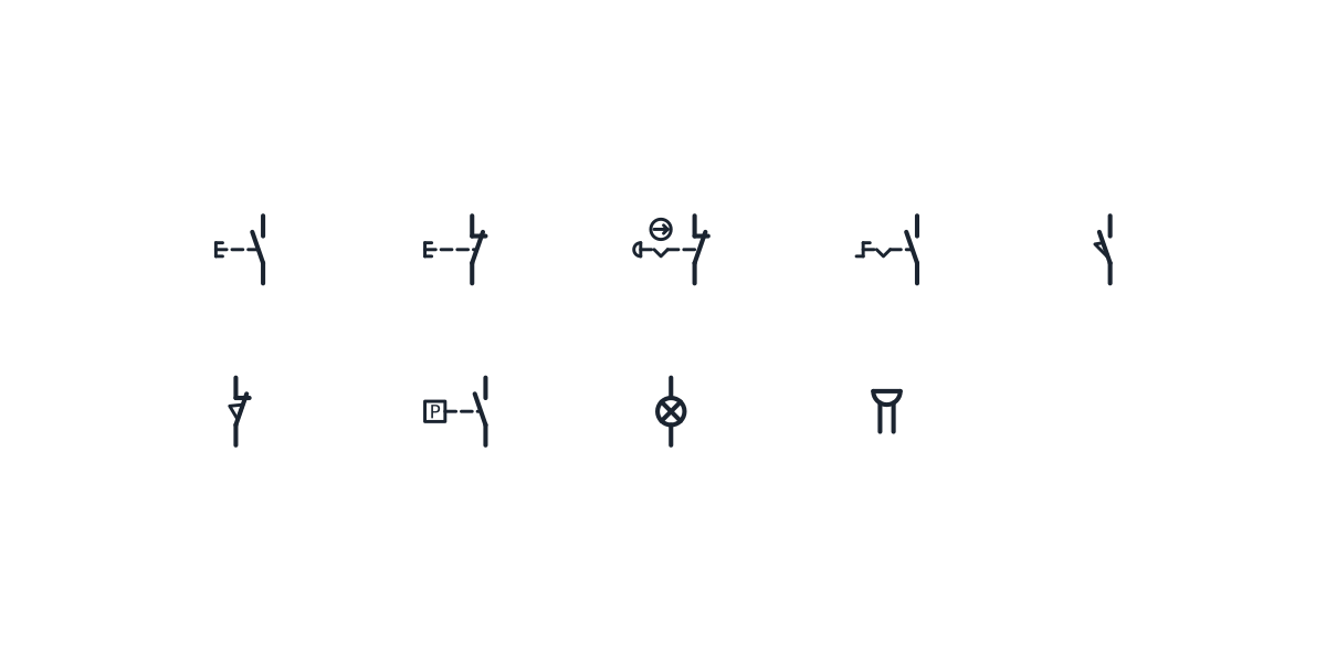
Push buttons, the emergency stop, selector and limit switches, a lamp and a buzzer as schematic CAD blocks.
Push button symbol library
-
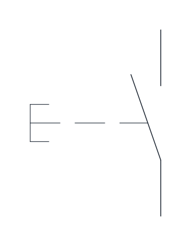
Pushbutton, normally open
A make contact operated by pushing, with automatic return. The typical start button of a control circuit.
IND_ELECTRICAL_SCHEMATIC_SYMBOLS_PUSHBUTTON_NO
-
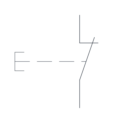
Pushbutton, normally closed
A break contact operated by pushing, with automatic return, used for stop buttons wired in series with the holding circuit.
IND_ELECTRICAL_SCHEMATIC_SYMBOLS_PUSHBUTTON_NC
-
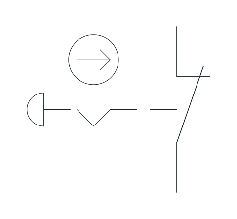
Emergency stop (mushroom head)
A break contact with a mushroom-head actuator, a latching notch and the positive opening mark. It stays latched once pressed and has to be reset by hand.
IND_ELECTRICAL_SCHEMATIC_SYMBOLS_EMERGENCY_STOP_MUSHROOM
-
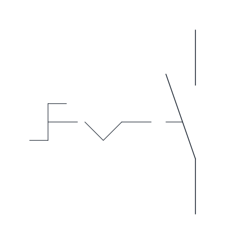
Selector switch
A make contact operated by turning, with a detent that holds the selected position, for mode choices such as manual and automatic.
IND_ELECTRICAL_SCHEMATIC_SYMBOLS_SELECTOR_SWITCH
-
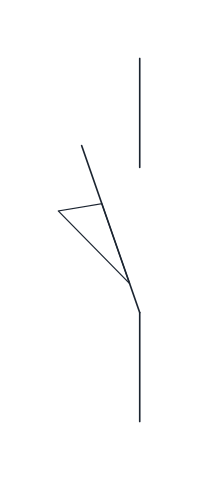
Limit switch, normally open
A position switch whose make contact closes when a moving part of the machine reaches it. The wedge on the blade marks mechanical actuation by position.
IND_ELECTRICAL_SCHEMATIC_SYMBOLS_LIMIT_SWITCH_NO
-
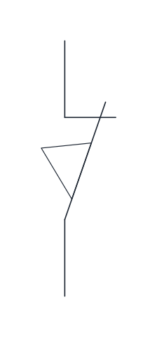
Limit switch, normally closed
A position switch whose break contact opens when the moving part reaches the end of its travel, often used to stop a drive.
IND_ELECTRICAL_SCHEMATIC_SYMBOLS_LIMIT_SWITCH_NC
-
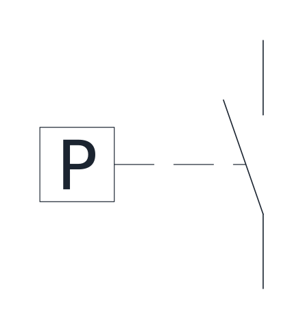
Pressure switch, normally open
A make contact operated by the pressure of a liquid or gas, which closes when the set pressure is reached. Used on compressors, pumps and hydraulic units.
IND_ELECTRICAL_SCHEMATIC_SYMBOLS_PRESSURE_SWITCH_NO
-
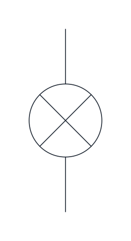
Signal lamp
A circle with a cross for an indicator or pilot lamp that shows a state such as running, fault or power on.
IND_ELECTRICAL_SCHEMATIC_SYMBOLS_SIGNAL_LAMP
-
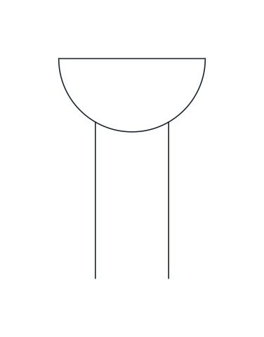
Buzzer
A semicircle with a flat top and two leads for an audible signalling device, often wired to a fault or alarm contact.
IND_ELECTRICAL_SCHEMATIC_SYMBOLS_BUZZER
- Units
- Millimetres (INSUNITS 4), drawn at paper size
- Formats
- DWG 2010 · DXF R2010 · PDF
- Opens in
- AutoCAD and AutoCAD LT 2010 or later, BricsCAD, ZWCAD and DraftSight. The DXF opens in most CAD programs.
- Views
- Sheet
- License
- Free for personal and commercial projects. License
The download brings together the push button symbol and the other manual and position controls of a machine schematic: normally open and normally closed push buttons, the mushroom-head emergency stop, a selector switch, normally open and normally closed limit switches, a pressure switch, a signal lamp and a buzzer. They are named blocks in DWG and DXF, with the names of the full schematic library, plus a PDF sheet.
Push button symbol: normally open and normally closed
A push button is a contact with an actuator drawn to its left, with a dashed link to the blade. Its shape shows operation by pushing, and the contact springs back when the button is released. The normally open button is the usual start command. The normally closed one is the stop. In the classic start and stop circuit, the stop button goes in series with the contactor coil, and the start button goes in parallel with a make contact of the same contactor, the holding contact, so the coil stays energised once the start button is released. The coil is on the relay symbol page. Push buttons and switches take the letter S in the reference designation.
Emergency stop symbol
The emergency stop is a normally closed contact with three extra marks: the mushroom head of the actuator, a latching notch that shows it stays pressed until someone resets it by hand, and the positive opening mark, a circle with an arrow, which says the contact is forced open by the actuator and does not rely on a spring. On the machine the actuator is red on a yellow background. On the drawing it is wired in series, so a broken wire stops the machine the same way a pressed button does.
Limit switch symbol and pressure switch
A limit switch is operated by a moving part of the machine, not by a person. The wedge drawn on the blade marks that mechanical actuation by position. The normally open version closes when the part arrives. The normally closed version opens at the end of travel and is often used to stop a drive. The pressure switch closes when the pressure of a liquid or a gas reaches its set point, as on compressors, pumps and hydraulic units.
Selector switch symbol for operating modes
A selector switch is operated by turning and has a detent that holds the chosen position. It is the usual way to choose between manual and automatic mode. Each position that does something is drawn as its own contact with the same reference designation.
Placing push button blocks with lamps and buzzers
The signal lamp, a circle with a cross, and the buzzer show a state or raise an alarm, and both take the letter P. Contacts and the lamp are in-line blocks: base point on the lower terminal, upper terminal 12.5 mm above it, on a 2.5 mm grid. The buzzer is placed by the end of its left lead, with both leads leaving downwards 2.5 mm apart. The full library and its grid are described on the electrical schematic symbols page.
Push buttons, switches and indicators are drawn after IEC 60617. IEC licenses that database for a fee instead of publishing it freely, so the forms here are a redrawing and not a copy.