Relay symbol: coil, contact and timer blocks for CAD
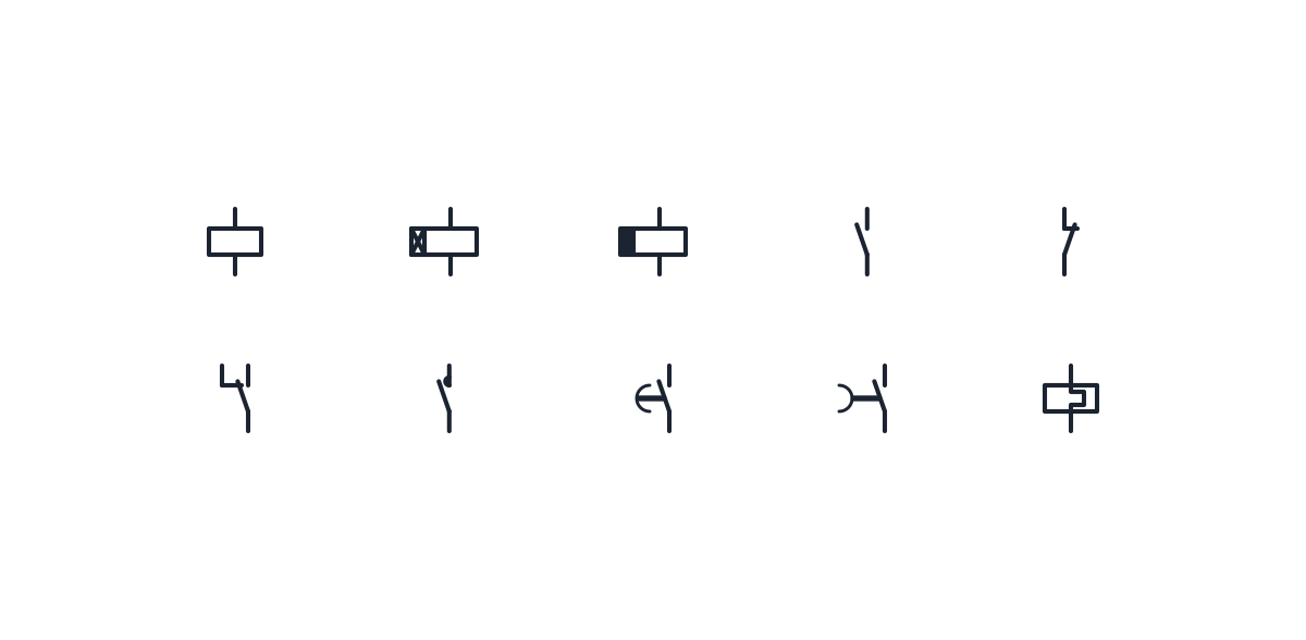
Coils, contacts, timer relays and the contactor main contact as IEC 60617 blocks for control schematics.
Relay symbol library
-
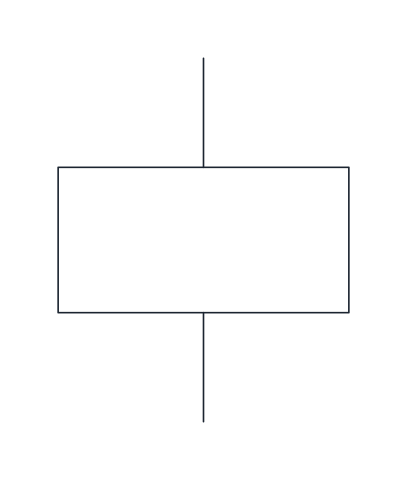
Relay or contactor coil
A rectangle for the operating coil of a relay or contactor. Its contacts are drawn elsewhere and share its reference designation.
IND_ELECTRICAL_SCHEMATIC_SYMBOLS_COIL
-
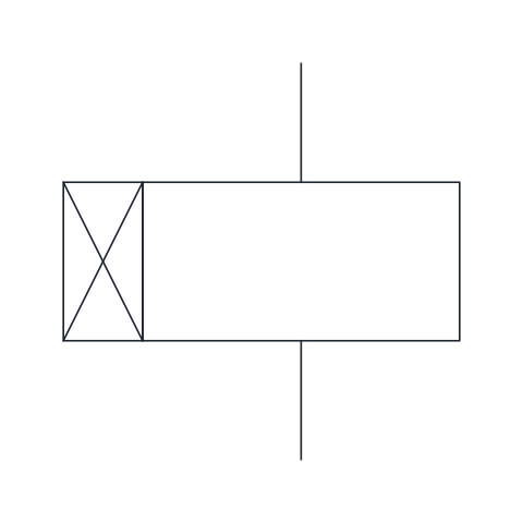
Coil, on-delay timer
Coil of a slow-operating relay, marked with a crossed box. Its contacts change state a set time after the coil is energized.
IND_ELECTRICAL_SCHEMATIC_SYMBOLS_COIL_TIME_DELAY_ON
-

Coil, off-delay timer
Coil of a slow-releasing relay, marked with a filled box. Its contacts return to rest a set time after the coil is de-energized.
IND_ELECTRICAL_SCHEMATIC_SYMBOLS_COIL_TIME_DELAY_OFF
-
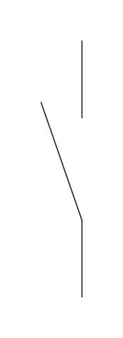
Normally open contact
A make contact, open at rest and closed when the device that drives it is actuated. It is the basic element for start commands and holding circuits.
IND_ELECTRICAL_SCHEMATIC_SYMBOLS_NO_CONTACT
-
Normally closed contact
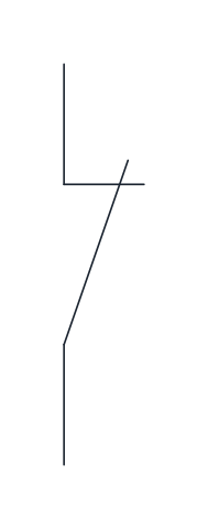
A break contact, closed at rest and opened on actuation. The blade crosses the hook of the fixed contact to show that it is touching.
IND_ELECTRICAL_SCHEMATIC_SYMBOLS_NC_CONTACT
-
Changeover contact
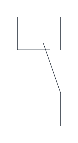
One moving blade shared by a break contact and a make contact, opening one before closing the other. Common on relays that switch between two circuits.
IND_ELECTRICAL_SCHEMATIC_SYMBOLS_CHANGEOVER_CONTACT
-
Contactor main contact
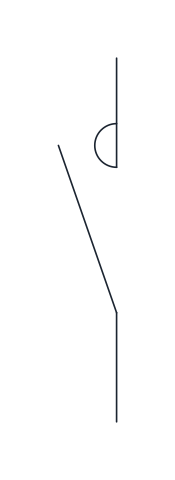
A make contact with a semicircle at the fixed contact, marking a main power contact of a contactor rated to switch motor or load currents.
IND_ELECTRICAL_SCHEMATIC_SYMBOLS_CONTACTOR_MAIN_CONTACT_NO
-
On-delay make contact
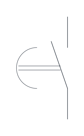
A make contact that closes after a set delay once the timer is energized and opens without delay when it is de-energized.
IND_ELECTRICAL_SCHEMATIC_SYMBOLS_TIME_DELAY_ON_NO_CONTACT
-
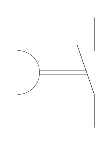
Off-delay make contact
A make contact that closes at once when the timer is energized and opens only after a set delay once it is de-energized.
IND_ELECTRICAL_SCHEMATIC_SYMBOLS_TIME_DELAY_OFF_NO_CONTACT
-
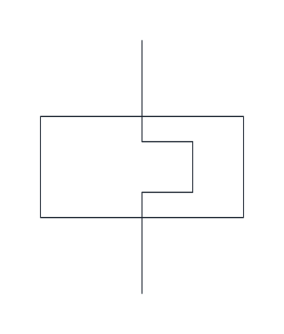
Thermal overload relay
The heating element of a thermal overload relay, drawn in the power circuit between the contactor and the motor. Its auxiliary contacts appear separately in the control circuit.
IND_ELECTRICAL_SCHEMATIC_SYMBOLS_THERMAL_OVERLOAD_RELAY
- Units
- Millimetres (INSUNITS 4), drawn at paper size
- Formats
- DWG 2010 · DXF R2010 · PDF
- Opens in
- AutoCAD and AutoCAD LT 2010 or later, BricsCAD, ZWCAD and DraftSight. The DXF opens in most CAD programs.
- Views
- Sheet
- License
- Free for personal and commercial projects. License
This download holds the relay symbol set for control schematics: the plain coil, the on-delay and off-delay timer coils, normally open, normally closed and changeover contacts, the contactor main contact, the two time delay contacts and the thermal overload relay. Each is a named block in the DWG and DXF, with the names of the full schematic library, plus a PDF chart.
Relay symbol: one coil, contacts drawn elsewhere
On an IEC schematic the coil, a rectangle, sits in the control circuit where it is switched, and each of its contacts appears in the circuit it switches. They belong together because they share the same reference designation, such as K1, and a cross-reference table under the coil lists where each contact is used. When the coil and a contact are drawn next to each other, a dashed mechanical link joins them. The rest-position rule is on the electrical schematic symbols page.
The terminals follow a fixed marking scheme. The coil is A1 and A2. Auxiliary contacts take two digits: the first counts the contact, the second gives its function, 1 and 2 for a normally closed contact, 3 and 4 for a normally open one. So 13-14 is the first make contact and 21-22 the second, a break contact. A changeover contact is numbered 11, 12 and 14 around its common terminal.
Contactor symbol and main contacts
A contactor is a relay built to switch power. Its coil is drawn with the same rectangle, but its main contacts carry a small semicircle at the fixed contact, and they are numbered 1-2, 3-4 and 5-6 for the three poles. In the reference designation scheme a contactor takes the letter Q, while a relay that only handles signals takes K.
Time delay relay symbol: on-delay and off-delay
The on-delay coil has a crossed box beside it and the off-delay coil a filled box. The contacts carry an arc, often called the parachute, that slows the blade in one direction: the movement is delayed in the direction that goes from the arc towards its centre. So the on-delay make contact closes late and opens at once, and the off-delay make contact closes at once and opens late.
Overload relay next to the contactor
The thermal overload relay block is the heating element that sits in the power circuit between the contactor and the motor. Its auxiliary contacts, usually 95-96 normally closed and 97-98 normally open, are drawn in the control circuit with the plain contact symbols. The 95-96 contact goes in series with the contactor coil.
Drawing relay circuits with these blocks
All blocks sit on a 2.5 mm grid with the current path vertical. The base point is the lower terminal and the upper terminal sits 12.5 mm above it, so coils and contacts drop onto vertical wires without adjusting. The changeover contact has its common terminal at the base point, the make terminal 12.5 mm above and the break terminal 5 mm to the left. For the start and stop buttons that drive the coil, see the push button symbol page.
Coils and contacts are drawn after IEC 60617. IEC sells access to that symbol database by subscription, and its official sheets are not reproduced here.