P&ID Symbols
40 P&ID symbols: valves, rotating equipment, vessels and exchangers after ISO 10628-2, and instrument bubbles after ISA-5.1.
P&ID Symbols library
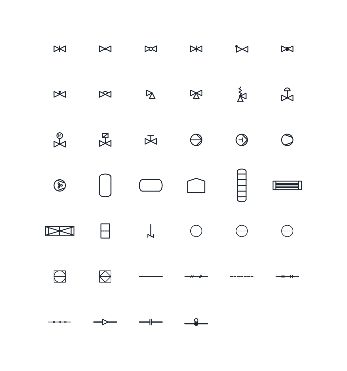
P&ID valve symbols
-
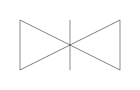
Gate valve
Two opposed triangles with a vertical bar through the centre for an on/off isolating valve whose gate slides across the flow. Use it for block valves that stay fully open or fully closed.
IND_PID_SYMBOLS_GATE_VALVE
-
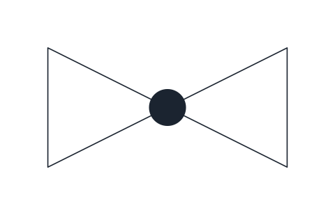
Globe valve
Valve body with a solid dot at the centre, marking a globe-pattern seat. Typical for throttling duties and bypasses where flow is adjusted by hand.
IND_PID_SYMBOLS_GLOBE_VALVE
-
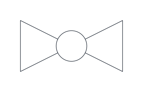
Ball valve
Valve body with an open circle at the centre for a quarter-turn valve with a bored ball. Common on utility lines and tight shut-off services.
IND_PID_SYMBOLS_BALL_VALVE
-
Butterfly valve
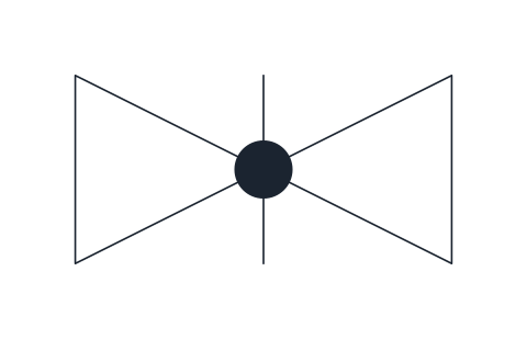
Valve body with a vertical bar and a centre dot representing the disc on its spindle. Used on large-bore lines for isolation or coarse throttling.
IND_PID_SYMBOLS_BUTTERFLY_VALVE
-
Check valve
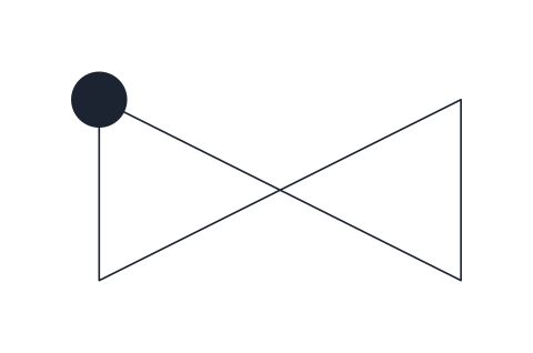
Valve body with a solid dot on the inlet corner, the general non-return valve. Draw it with the inlet on the left so the permitted flow runs left to right.
IND_PID_SYMBOLS_CHECK_VALVE
-
Plug valve
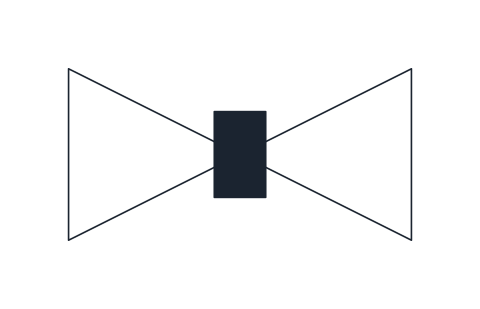
Valve body with a solid rectangle at the centre standing for the rotating plug. Used for quarter-turn isolation on slurries, gas and viscous fluids.
IND_PID_SYMBOLS_PLUG_VALVE
-
Needle valve
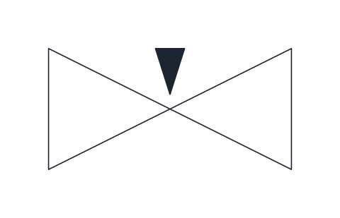
Valve body with a small solid wedge pointing into the seat, for fine flow adjustment on instrument connections, sampling points and small bleed lines.
IND_PID_SYMBOLS_NEEDLE_VALVE
-
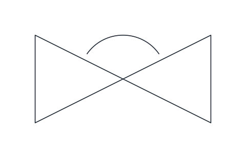
Diaphragm valve
Valve body with an arc over the centre representing the flexible diaphragm that closes onto a weir. Chosen for corrosive, abrasive or hygienic services.
IND_PID_SYMBOLS_DIAPHRAGM_VALVE
-
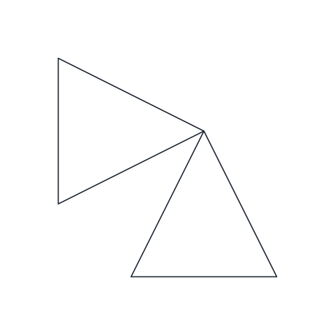
Angle valve
Two triangles at right angles: the flow enters from the left and leaves downward, or the reverse. Use it where the valve also turns the line through 90 degrees.
IND_PID_SYMBOLS_ANGLE_VALVE
-
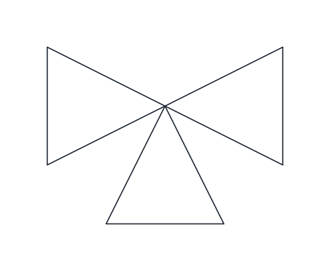
Three-way valve
In-line valve body with a third port pointing down, for diverting one stream into two or mixing two streams into one.
IND_PID_SYMBOLS_THREE_WAY_VALVE
-
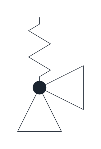
Safety relief valve
Angle valve with a spring above it: the inlet comes from the protected equipment below and the discharge leaves to the side. Marks a pressure relief device set to open on overpressure.
IND_PID_SYMBOLS_SAFETY_RELIEF_VALVE
-
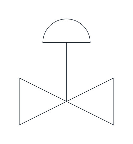
Control valve, diaphragm actuator
Valve body with a stem and a domed spring-and-diaphragm actuator on top. The standard way to show an air-operated modulating control valve in a control loop.
IND_PID_SYMBOLS_CONTROL_VALVE_PNEUMATIC
-
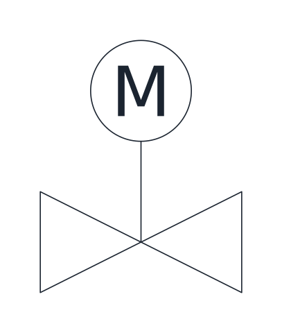
Control valve, electric motor actuator
Valve body with a stem and a circle marked M for an electric motor actuator. Used for motor-operated valves, whether on/off or modulating.
IND_PID_SYMBOLS_CONTROL_VALVE_MOTOR
-
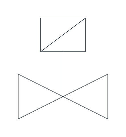
Solenoid valve
Valve body with a stem and a rectangle crossed by a diagonal, the electromagnetic actuator. Shows an electrically switched on/off valve, often on pilot air or small process lines.
IND_PID_SYMBOLS_SOLENOID_VALVE
-
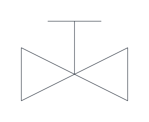
Hand-operated valve
Valve body with a stem ending in a T-bar for a handwheel. Use it where the drawing needs to state explicitly that the valve is operated by hand.
IND_PID_SYMBOLS_MANUAL_VALVE_HANDWHEEL
Pump and equipment symbols
-
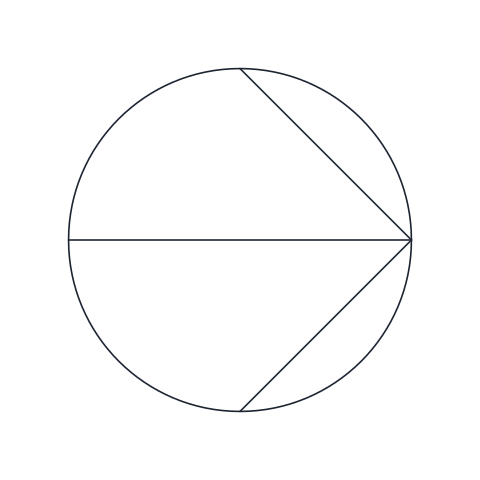
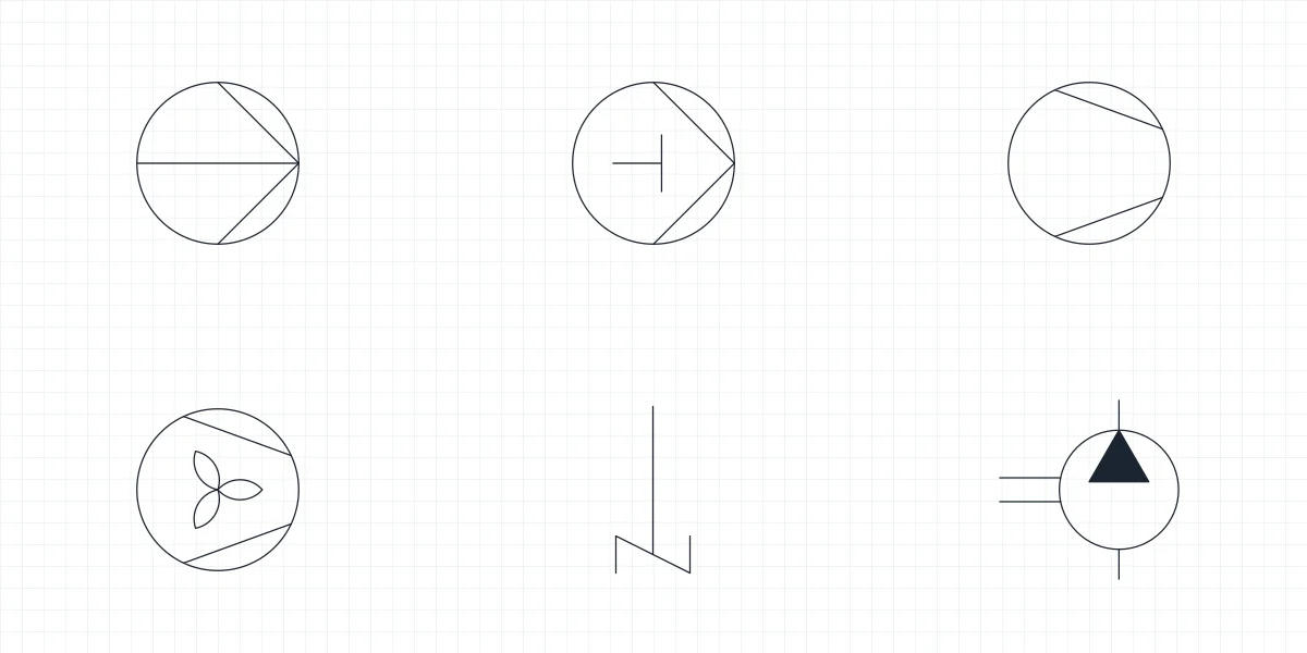
Centrifugal pump
Circle with two lines converging on the discharge side and a horizontal diameter, the centrifugal variant of the liquid pump. Rotate the block so the converging point faces the discharge.
IND_PID_SYMBOLS_CENTRIFUGAL_PUMP
-
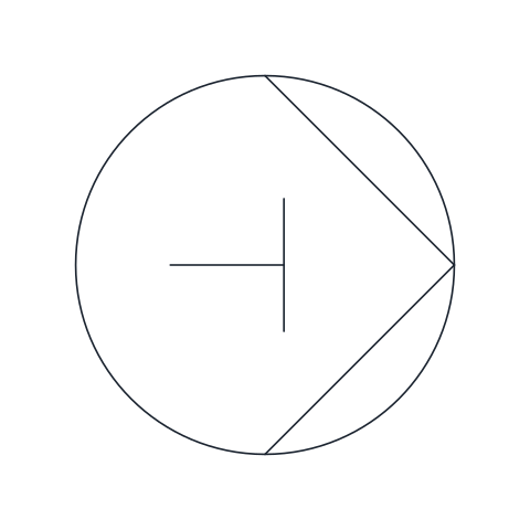
Positive displacement pump (reciprocating)
Liquid pump outline with a piston and rod drawn inside, the reciprocating positive displacement form. Suitable for metering, dosing and high-pressure duties.
IND_PID_SYMBOLS_POSITIVE_DISPLACEMENT_PUMP
-
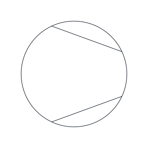
Compressor
Circle with two chords that narrow towards the outlet, the general symbol for a gas compressor or vacuum pump. The narrow end faces the high-pressure side.
IND_PID_SYMBOLS_COMPRESSOR
-
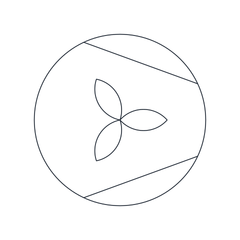
Fan or blower
Compressor-style circle with a three-blade impeller inside, for fans and blowers moving gas at low pressure rise such as ventilation, combustion air or drying air.
IND_PID_SYMBOLS_FAN_BLOWER
-
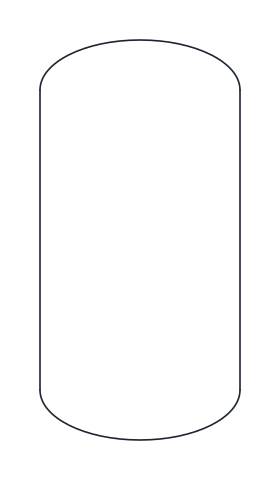
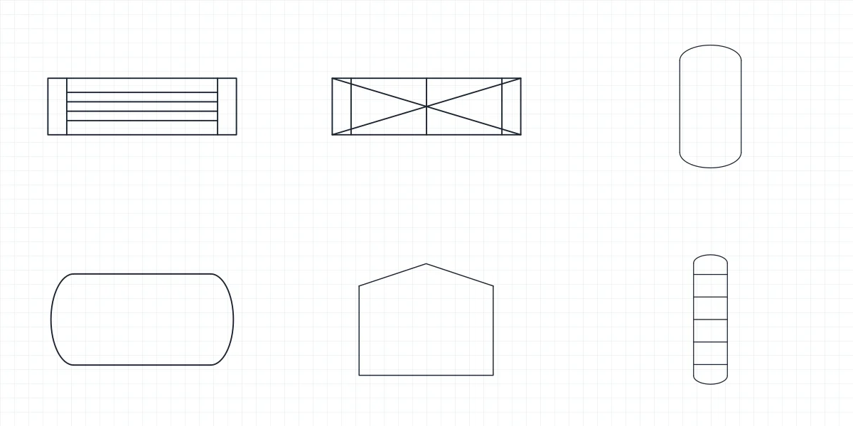
Vertical vessel
Upright cylindrical vessel with dished heads at both ends. Use it for drums, receivers, separators and reactors standing on end.
IND_PID_SYMBOLS_VERTICAL_VESSEL
-
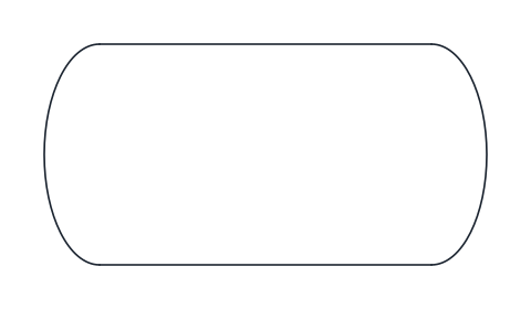
Horizontal vessel
Cylindrical vessel lying on its side with dished heads, for accumulators, storage drums and horizontal separators.
IND_PID_SYMBOLS_HORIZONTAL_VESSEL
-
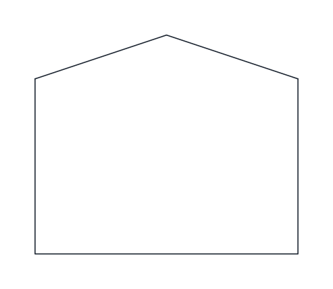
Atmospheric storage tank
Flat-bottomed tank with a low conical roof, the usual picture of a storage tank working at or near atmospheric pressure.
IND_PID_SYMBOLS_ATMOSPHERIC_TANK
-
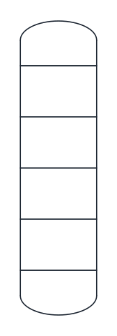
Tray column
Tall vessel with dished heads and horizontal lines for trays, used for distillation, absorption and stripping columns. Remove or add tray lines to match the drawing scale.
IND_PID_SYMBOLS_COLUMN
-
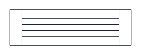
Shell and tube heat exchanger
Long rectangle with a tube sheet near each end and a bundle of straight tubes between them. Represents a fixed tube-sheet exchanger; connect the shell-side and tube-side lines to the matching faces.
IND_PID_SYMBOLS_SHELL_TUBE_HEAT_EXCHANGER
-
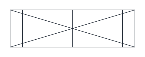
Plate heat exchanger
Rectangle with three cross bars and a full diagonal cross, for gasketed or brazed plate exchangers that pass two fluids through alternate channels.
IND_PID_SYMBOLS_PLATE_HEAT_EXCHANGER
-
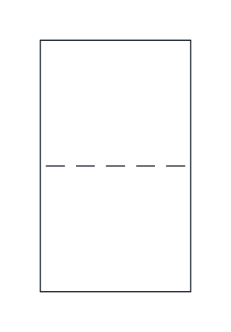
Liquid filter
Upright housing with a dashed line across it for the filter element. Use it for in-line liquid filters and cartridge housings when the filter type need not be detailed.
IND_PID_SYMBOLS_FILTER
-
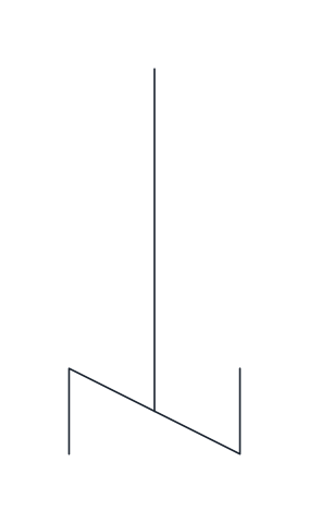
Agitator
Vertical shaft ending in an angled blade, the general stirrer symbol. Insert it at the top of a vessel so the shaft enters through the head; the base point is the top of the shaft.
IND_PID_SYMBOLS_AGITATOR
Instrument symbols
-

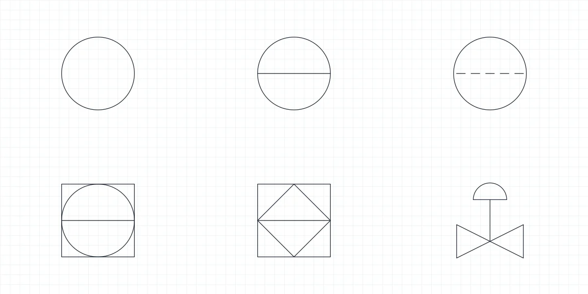
Field-mounted instrument
Plain circle for a discrete instrument mounted in the field, close to the process. Fill in the FUNCTION attribute with the identification letters and LOOP with the loop number.
IND_PID_SYMBOLS_INSTRUMENT_FIELD
-
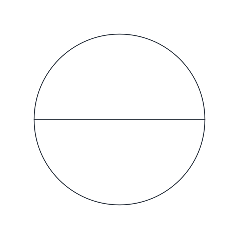
Panel-mounted instrument
Circle with a solid horizontal line, for a discrete instrument in a primary location such as the control room panel, normally accessible to the operator.
IND_PID_SYMBOLS_INSTRUMENT_PANEL
-
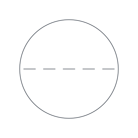
Instrument behind the panel
Circle with a dashed horizontal line, for a discrete instrument in a primary location that is not normally accessible to the operator, such as inside a cabinet or behind the panel.
IND_PID_SYMBOLS_INSTRUMENT_BEHIND_PANEL
-
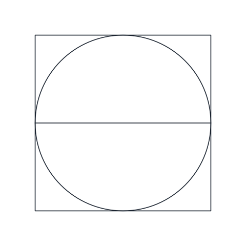
Shared display or control (DCS)
Circle inside a square with a solid horizontal line, for a function shown or controlled on a shared display, typically a DCS operator station in the control room.
IND_PID_SYMBOLS_INSTRUMENT_DCS
-
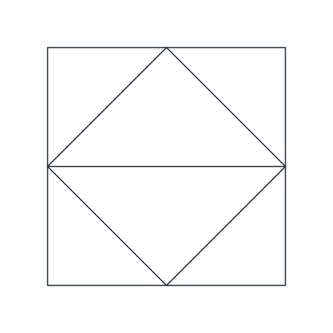
PLC function
Diamond inside a square with a solid horizontal line, for a function performed by a programmable logic controller and accessible to the operator.
IND_PID_SYMBOLS_INSTRUMENT_PLC
Piping and line symbols
-

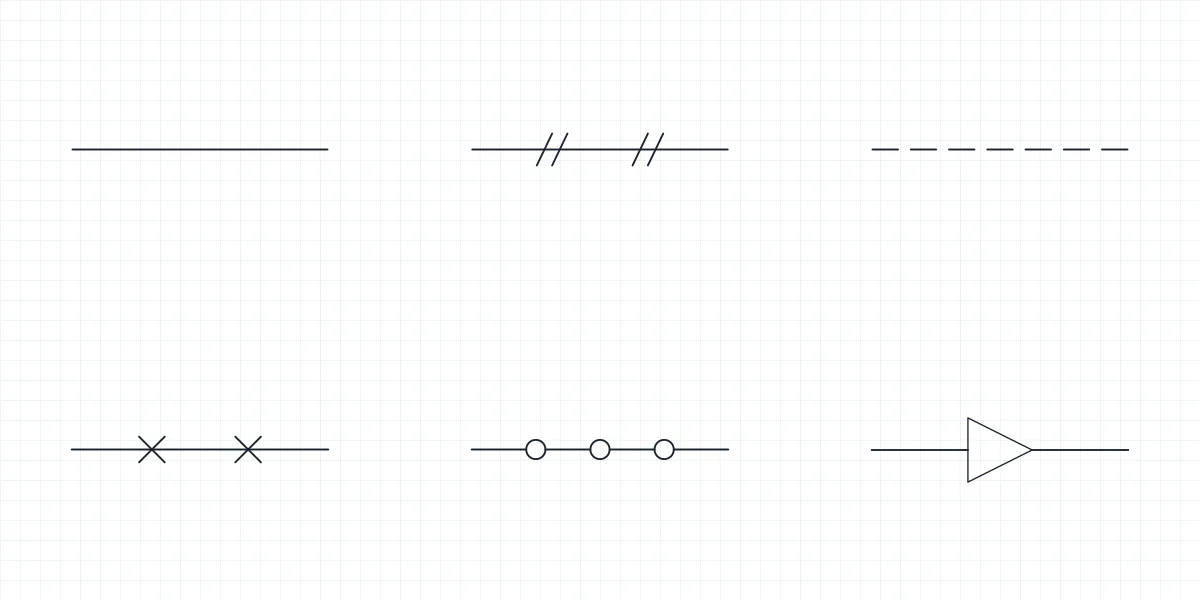
Process line
Heavy solid line for main process piping. Draw it on the process line layer so it stays thicker than signal and utility lines.
IND_PID_SYMBOLS_LINE_PROCESS
-
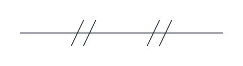
Pneumatic signal line
Thin solid line with pairs of short slashes, for an instrument air signal between a transmitter, controller and actuator.
IND_PID_SYMBOLS_LINE_PNEUMATIC_SIGNAL
-

Electrical signal line
Dashed line for an electrical or electronic signal, such as a 4-20 mA loop between a field transmitter and the control system.
IND_PID_SYMBOLS_LINE_ELECTRICAL_SIGNAL
-
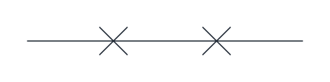
Capillary tube
Thin line with small crosses, for a filled capillary system linking a sensing bulb or remote seal to its instrument.
IND_PID_SYMBOLS_LINE_CAPILLARY
-
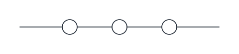
Data link
Thin line interrupted by small circles, for a communication or software link between systems, such as a fieldbus or a link between a PLC and the DCS.
IND_PID_SYMBOLS_LINE_DATA_LINK
-
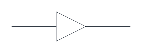
Reducer
Triangle on the line marking a change of pipe size, with the wide side towards the larger bore. Flip the block to match the direction of reduction.
IND_PID_SYMBOLS_REDUCER
-
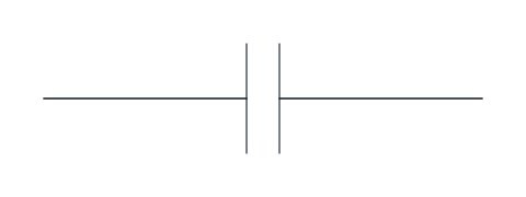
Flanged connection
Two short parallel bars across the line for a bolted flange joint. Use it where a joint must be shown, for example at equipment nozzles or removable spools.
IND_PID_SYMBOLS_FLANGE_PAIR
-

Spectacle blind
Solid disc on the line with an open ring beside it, a spectacle blind drawn in the closed position. Swap the disc and ring to show it open.
IND_PID_SYMBOLS_SPECTACLE_BLIND
- Units
- Millimetres (INSUNITS 4), drawn at paper size
- Formats
- DWG 2010 · DXF R2010 · PDF
- Opens in
- AutoCAD and AutoCAD LT 2010 or later, BricsCAD, ZWCAD and DraftSight. The DXF opens in most CAD programs.
- Views
- Sheet
- License
- Free for personal and commercial projects. License
This library holds the P&ID symbols you need to draw a process: valves, pumps and compressors, vessels and heat exchangers, instrument bubbles and line types. Equipment, valves and lines follow ISO 10628-2, and the instrument bubbles follow ISA-5.1. Every symbol is a named block in the DWG and DXF, and the PDF sheet is a printable legend of all of them.
Valve symbols on a P&ID
Most valve symbols start from the same body, two triangles meeting at their points, and add a mark that tells the type apart. In this library the gate valve carries a straight bar through the body, the globe valve a filled dot at the centre, the ball valve an open circle, the butterfly valve a bar with a dot and the check valve a dot on the inlet side. The plug valve has a filled rectangle, the needle valve a small filled triangle and the diaphragm valve an arc over the body. A three-way valve adds a third triangle, the angle valve turns the outlet through 90 degrees and the safety relief valve shows its spring. Control valves carry their actuator on a stem: a dome for a pneumatic diaphragm, a circle with an M for an electric motor and a square with a diagonal for a solenoid.
All in-line valves in the library have the same length and height, so they drop into a process line drawn on a 2.5 mm grid without breaking it.
Pump and vessel symbols in a P&ID
The centrifugal pump is a circle with two lines converging on the discharge, and positive displacement pumps, compressors and fans have their own forms. Vessels are drawn by their outline: vertical and horizontal vessels with dished heads, the atmospheric tank with a flat roof and the column. The shell and tube heat exchanger, the plate heat exchanger, the filter and the agitator complete the equipment group.
Instrument symbols on a P&ID
ISA-5.1 places every instrument in a bubble, and the lines inside it say where the instrument is. A plain circle is mounted in the field. A circle with a solid horizontal line sits on the main control panel, where the operator can reach it, and a dashed line means it is mounted behind the panel. A circle inside a square is a function on a shared display, typically a DCS, and a diamond inside a square is a PLC function.
The bubble holds a tag. The first letter is the measured variable, such as F for flow, L for level, P for pressure and T for temperature, and the following letters are the functions, such as I for indicate, T for transmit and C for control. A flow indicating controller is FIC, a level transmitter is LT. The loop number goes below. Each bubble in the library has two attributes, FUNCTION and LOOP, so AutoCAD asks for them on insert.
Line types on a P&ID
Process lines are continuous and thicker than signal lines. Pneumatic signals, electrical signals, capillary tubing and data links each have their own line pattern. The library includes short samples of each, plus the reducer, the flanged joint and the spectacle blind, so you can copy the line style into your own drawing.
Using the P&ID symbols in AutoCAD
Valves and in-line items have their base point at the left connection, on the line, and equipment and bubbles at their centre. The angle and three-way valves have their lower port 5 mm below the centre, and the agitator is placed by the top of its shaft. Insert them from DesignCenter (ADCENTER), or copy the blocks from the DXF into any CAD program. The DWG is saved for AutoCAD 2010 and later.
ISO 10628-2 and ISA-5.1 are sold by their publishers and are not reproduced here. Many operators have their own legend sheet, so when a project has one it takes priority over any generic library.
P&ID symbol libraries by equipment type
- Valve Symbols: Fifteen P&ID valve symbols on one body size, from the gate valve to control valves with their actuators.
- Check Valve Symbols: The check valve as drawn on a P&ID and in hydraulic and pneumatic circuits, with the valves that carry a check element.
- Pump Symbol: Centrifugal and reciprocating pumps, compressor, fan and agitator for P&IDs, plus the hydraulic pump and pneumatic compressor.
- Instrumentation Symbols: ISA-5.1 instrument bubbles with FUNCTION and LOOP attributes, loop valves and the four signal line types.
- Heat Exchanger Symbol: Shell and tube and plate exchangers with the vessels, tank, column and filter that sit beside them on a P&ID.
- Piping Symbols: Process and signal line types, reducer, flanged joint, spectacle blind and four in-line valves for P&IDs.