Check Valve Symbols
The check valve as drawn on a P&ID and in hydraulic and pneumatic circuits, with the valves that carry a check element.
Check valve symbols library
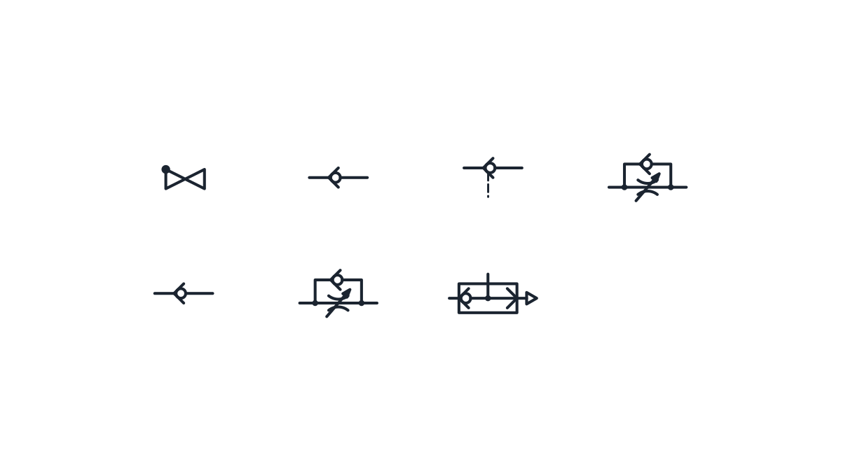
P&ID symbols
-
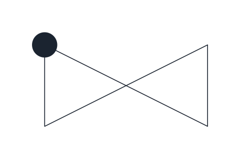
Check valve
Valve body with a solid dot on the inlet corner, the general non-return valve. Draw it with the inlet on the left so the permitted flow runs left to right.
IND_PID_SYMBOLS_CHECK_VALVE
Hydraulic symbols
-
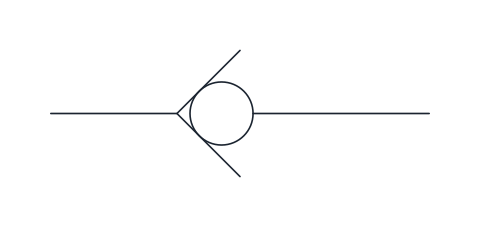
Check valve
Ball pressed against a seat that lets flow pass from left to right and blocks the reverse direction. Draw it wherever the circuit must stop back-flow, for example at a pump outlet.
IND_HYDRAULIC_SYMBOLS_CHECK_VALVE
-
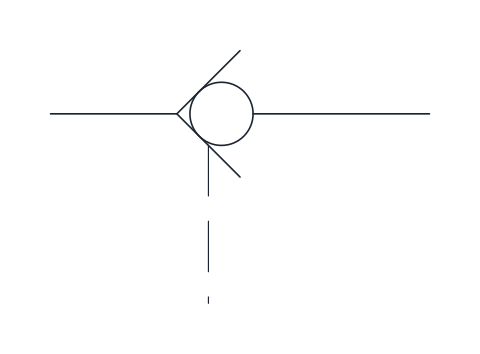
Pilot-operated check valve
Check valve that a pilot signal, drawn as the dashed line at the seat, can open to allow reverse flow. It holds a cylinder load without leakage until the pilot line is pressurised.
IND_HYDRAULIC_SYMBOLS_PILOT_OPERATED_CHECK_VALVE
-
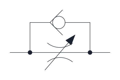
One-way flow control valve
Adjustable throttle with a check valve in parallel: flow is restricted in one direction and passes freely through the check valve in the other. The usual way to set the speed of a cylinder in one stroke only.
IND_HYDRAULIC_SYMBOLS_ONE_WAY_FLOW_CONTROL_VALVE
Pneumatic symbols
-
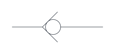
Check valve
Ball against a seat that lets air pass from left to right and blocks the reverse direction. Used to hold pressure in a branch or keep flow one-way.
IND_PNEUMATIC_SYMBOLS_CHECK_VALVE
-
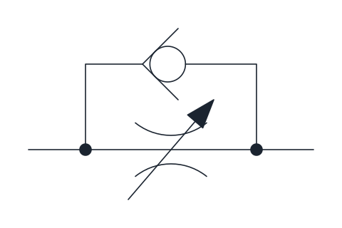
One-way flow control valve
Adjustable throttle with a check valve in parallel, restricting flow in one direction only. Fitted at cylinder ports to set the piston speed, usually by throttling the exhaust air.
IND_PNEUMATIC_SYMBOLS_ONE_WAY_FLOW_CONTROL_VALVE
-
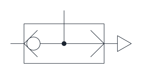
Quick exhaust valve
Ball valve that feeds the outlet from the inlet and, when the inlet drops, vents the outlet straight to atmosphere. Mounted close to a cylinder port to increase piston speed.
IND_PNEUMATIC_SYMBOLS_QUICK_EXHAUST_VALVE
- Units
- Millimetres (INSUNITS 4), drawn at paper size
- Formats
- DWG 2010 · DXF R2010 · PDF
- Opens in
- AutoCAD and AutoCAD LT 2010 or later, BricsCAD, ZWCAD and DraftSight. The DXF opens in most CAD programs.
- Views
- Sheet
- License
- Free for personal and commercial projects. License
This download collects check valve symbols from three kinds of drawing in one file: the P&ID check valve, the hydraulic check valve and pilot-operated check valve, the pneumatic check valve, and the valves that carry a check element inside them, the one-way flow control valve in both media and the pneumatic quick exhaust valve. That is 7 named blocks in DWG and DXF and a PDF sheet. Each block keeps its library name, such as IND_PID_SYMBOLS_CHECK_VALVE or IND_HYDRAULIC_SYMBOLS_PILOT_OPERATED_CHECK_VALVE.
Check valve symbol on a P&ID
On a piping and instrumentation diagram the check valve uses the common valve body, two triangles point to point, with a solid dot on the upper corner of the inlet side. Flow is allowed from left to right. The body is 10 mm long and 5 mm high like every in-line valve in the P&ID set, with the base point on the left connection, so it replaces a gate or globe valve on the same line. If the flow runs the other way, mirror the block rather than drawing a new one.
Some company legends draw a swing disc or add a flow arrow. This block keeps the plain form, so if a project legend asks for something else, that legend wins.
Non-return valve symbol in hydraulics and pneumatics
In fluid power circuits the same device is usually called a non-return valve. It is drawn as a ball resting in a V-shaped seat: flow that pushes the ball off the seat passes, from left to right here, and reverse flow presses it shut. The hydraulic and pneumatic blocks have the same geometry, 15 mm long, and live in both libraries so that each one is complete on its own. Insert them by the left connection.
Pilot operated check valve symbol
The pilot-operated check valve adds a dashed pilot line that reaches the seat from below. Pressure in that line lifts the ball and lets the fluid return. The usual place is between a directional valve and a cylinder that has to hold a load without creeping: the cylinder only moves back when the pilot line is pressurised. Here it is drawn without a spring and without an enclosing frame, both of which some charts show.
Check valves inside flow control and quick exhaust valves
The one-way flow control valve is an adjustable throttle with a check valve in parallel. Flow is restricted in one direction and passes freely through the check element in the other, which sets cylinder speed on one stroke only. In pneumatics it is normally fitted to throttle the exhaust air. The quick exhaust valve takes air in on the left, feeds the outlet on top, and when the inlet drops it vents the outlet straight to atmosphere on the right, so mount it close to the cylinder port.
The other in-line valves of a process drawing are on the valve symbols page, the valves that switch the cylinder are among the directional control valve symbols, and the complete process set is the P&ID symbols library.
The P&ID block follows ISO 10628-2 and the fluid power blocks follow ISO 1219-1. Both standards are sold by ISO; we only redraw their conventions and do not reproduce them.