Directional Control Valve Symbols
Hydraulic and pneumatic directional control valves, from 2/2 to 5/3, with seven actuators placed by a fixed corner.
Directional control valve symbols library
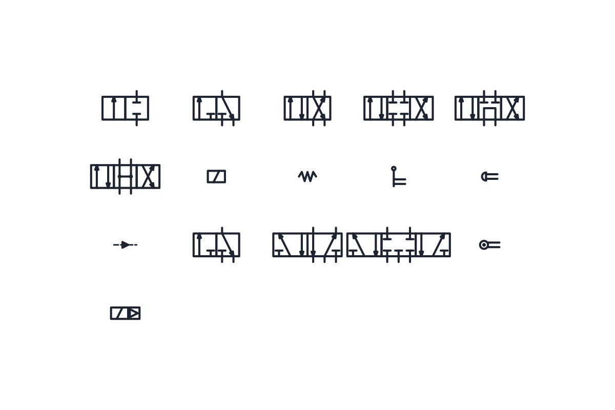
Hydraulic symbols
-
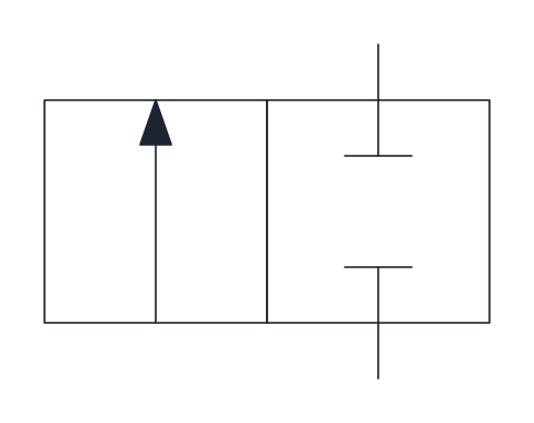
2/2 directional control valve
Two-port, two-position valve shown normally closed, with flow from P to A in the actuated position. Works as an on/off valve; add the actuator and return spring blocks beside the boxes.
IND_HYDRAULIC_SYMBOLS_DCV_2_2
-
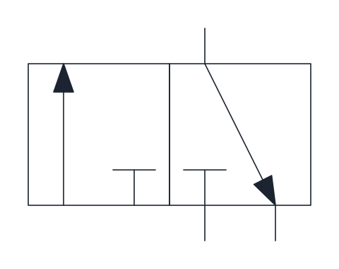
3/2 directional control valve
Three-port, two-position valve shown normally closed: at rest A is connected to tank and P is blocked, when actuated P feeds A. Typical for single-acting cylinders and pilot signals.
IND_HYDRAULIC_SYMBOLS_DCV_3_2
-
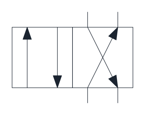
4/2 directional control valve
Four-port, two-position valve that switches P and T between ports A and B, so a double-acting cylinder extends or retracts. Ports are drawn on the right-hand box, the rest position.
IND_HYDRAULIC_SYMBOLS_DCV_4_2
-
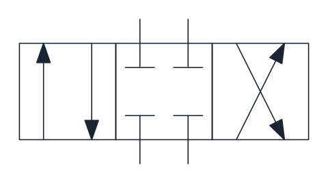
4/3 directional control valve, closed centre
Three-position valve whose centre position blocks P, T, A and B, holding the actuator in place. Suited to circuits where several valves share one pump with an accumulator or a pressure-compensated pump.
IND_HYDRAULIC_SYMBOLS_DCV_4_3_CLOSED_CENTRE
-
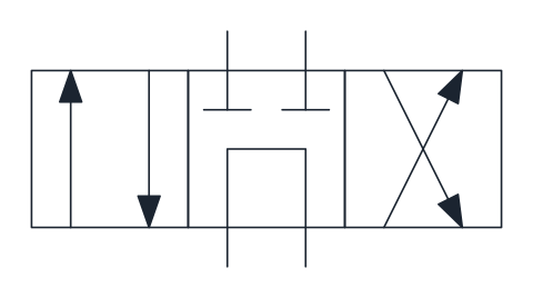
4/3 directional control valve, tandem centre
Three-position valve whose centre connects P to T and blocks A and B, so the pump unloads to tank while the actuator stays locked. A common choice with fixed displacement pumps.
IND_HYDRAULIC_SYMBOLS_DCV_4_3_TANDEM_CENTRE
-
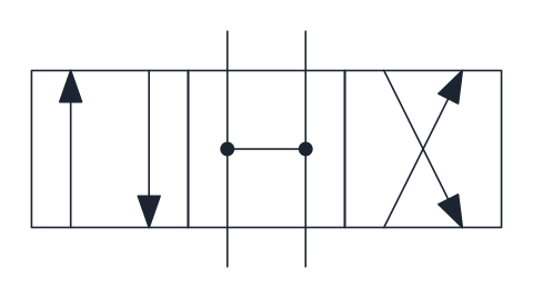
4/3 directional control valve, open centre
Three-position valve whose centre position connects all four ports, unloading the pump and leaving the actuator free to move. Used where the load may float when the valve is in neutral.
IND_HYDRAULIC_SYMBOLS_DCV_4_3_OPEN_CENTRE
-
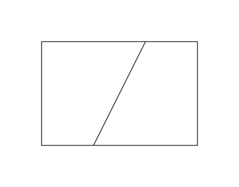
Solenoid actuator
Rectangle with an oblique line for direct electrical operation by a single winding. Attach it to the outer side of the end box it shifts.
IND_HYDRAULIC_SYMBOLS_ACTUATOR_SOLENOID
-
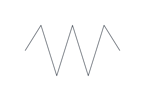
Return spring
Zigzag spring that returns the valve to its rest position when the other actuator releases. Drawn for the right-hand side of the valve; mirror it for the left.
IND_HYDRAULIC_SYMBOLS_ACTUATOR_SPRING
-
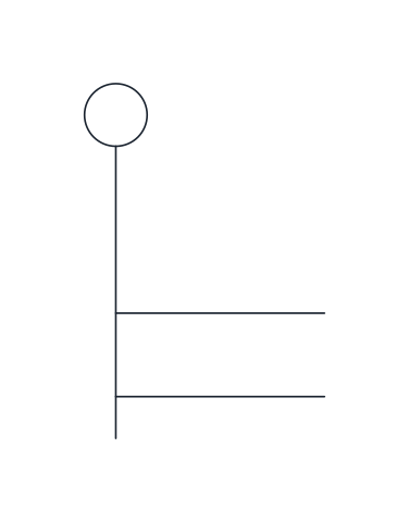
Lever actuator
Manual operation by a hand lever, shown as the operating stem with a lever ending in a small circle. Used on mobile and manually operated valves.
IND_HYDRAULIC_SYMBOLS_ACTUATOR_LEVER
-
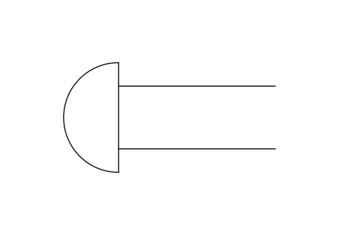
Push-button actuator
Manual operation by a push button, drawn as the operating stem capped with a rounded head. Usually combined with a return spring on the opposite side.
IND_HYDRAULIC_SYMBOLS_ACTUATOR_PUSHBUTTON
-
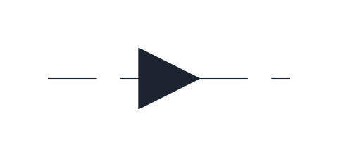
Hydraulic pilot actuator
Direct pilot operation: a dashed pilot line with a filled triangle pointing at the valve shows that pilot pressure shifts the spool. Used when another valve or a pressure signal controls the main valve.
IND_HYDRAULIC_SYMBOLS_ACTUATOR_PILOT
Pneumatic symbols
-
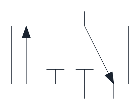
3/2 directional control valve
Three-port, two-position valve shown normally closed: at rest port 2 exhausts to 3 and supply 1 is blocked, when actuated 1 feeds 2. Used for single-acting cylinders and signal generation.
IND_PNEUMATIC_SYMBOLS_DCV_3_2
-
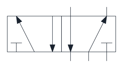
5/2 directional control valve
Five-port, two-position valve with two outputs and two exhausts; supply 1 switches between outputs 2 and 4. The standard valve for double-acting pneumatic cylinders.
IND_PNEUMATIC_SYMBOLS_DCV_5_2
-
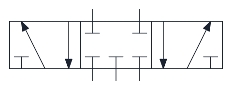
5/3 directional control valve, closed centre
Three-position valve whose centre position blocks all five ports, trapping air in both cylinder chambers. Used to stop a cylinder in mid-stroke.
IND_PNEUMATIC_SYMBOLS_DCV_5_3_CLOSED_CENTRE
-
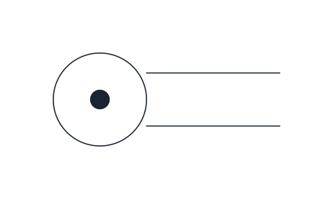
Roller actuator
Mechanical operation by a roller on the end of the plunger, drawn as a circle with a centre dot. Used for limit valves that a moving cam or machine part actuates.
IND_PNEUMATIC_SYMBOLS_ACTUATOR_ROLLER
-
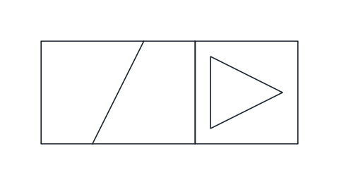
Solenoid with pilot actuation
Solenoid that switches an internal pilot stage, which then shifts the main valve with air pressure, drawn as the coil next to a box with an open triangle. The usual operator on solenoid valves for larger flows.
IND_PNEUMATIC_SYMBOLS_ACTUATOR_SOLENOID_PILOT
- Units
- Millimetres (INSUNITS 4), drawn at paper size
- Formats
- DWG 2010 · DXF R2010 · PDF
- Opens in
- AutoCAD and AutoCAD LT 2010 or later, BricsCAD, ZWCAD and DraftSight. The DXF opens in most CAD programs.
- Views
- Sheet
- License
- Free for personal and commercial projects. License
This download holds 16 directional control valve symbols as named blocks in DWG and DXF, plus a PDF sheet: the hydraulic 2/2, 3/2, 4/2 and three 4/3 valves, the pneumatic 3/2, 5/2 and 5/3, and seven actuators to mount on them. Block names match the full libraries, such as IND_PNEUMATIC_SYMBOLS_DCV_5_2.
How directional control valve symbols are drawn
Each switching position is one square, and the squares sit side by side. Arrows inside a square show which ports are joined in that position, and a short cross bar marks a blocked port. The external lines touch only one square, the rest position: the right-hand square on the two-position hydraulic valves in this set, and the centre square on the 4/3 valves.
Hydraulic ports are lettered P, T, A and B. The 2/2 and 3/2 are drawn normally closed. On the 4/2, and on the ends of the 4/3, one square runs P to A and B to T and the other crosses them.
4/3 valve symbols: closed, tandem and open centre
The centre square decides what the circuit does when nothing is switched. The closed centre blocks all four ports and holds the actuator in place, which suits several valves sharing a pressure-compensated pump. The tandem centre joins P to T and blocks A and B, so the pump unloads to tank while the load stays locked, a usual pairing with a fixed displacement pump. The open centre connects all four ports and lets the actuator float.
5/2 valve symbol and the other pneumatic valves
Pneumatic ports are numbered: 1 supply, 2 and 4 outputs, 3 and 5 exhausts. In the 5/2 valve the rest square joins 1 to 2 and 4 to 5, and the actuated square joins 1 to 4 and 2 to 3, which is why the two ends are called the 12 side and the 14 side. It is the normal valve for a double-acting cylinder. The 5/3 closed centre traps air in both chambers to stop a cylinder mid-stroke. Five-port squares are 15 mm wide and 10 mm high, the rest 10 x 10 mm.
Valve actuator symbols and where to insert them
The hydraulic actuators are solenoid, return spring, lever, push button and pilot. The pneumatic set adds a roller and a solenoid with pilot stage. Each actuator fills the lower half of the square's side and its base point is the lower outer corner of the end square. All are drawn for the left end except the spring, so mirror a block for the other side.
Measured from the valve's base point, on port P or port 1 of the rest square, the left and right corners sit 2.5 mm up and at -15 and +5 mm on the 2/2, -12.5 and +7.5 mm on the 3/2 and 4/2, -12.5 and +17.5 mm on the 4/3, -22.5 and +7.5 mm on the 5/2 and -22.5 and +22.5 mm on the 5/3. The rest of the circuit is in the hydraulic symbols library, with the hydraulic pump symbol and the check valve symbols that often sit between valve and cylinder.
The conventions come from ISO 1219-1, which ISO publishes and sells; none of its text is copied here. Check the blocks against the edition your client asks for.