Hydraulic Pump Symbol
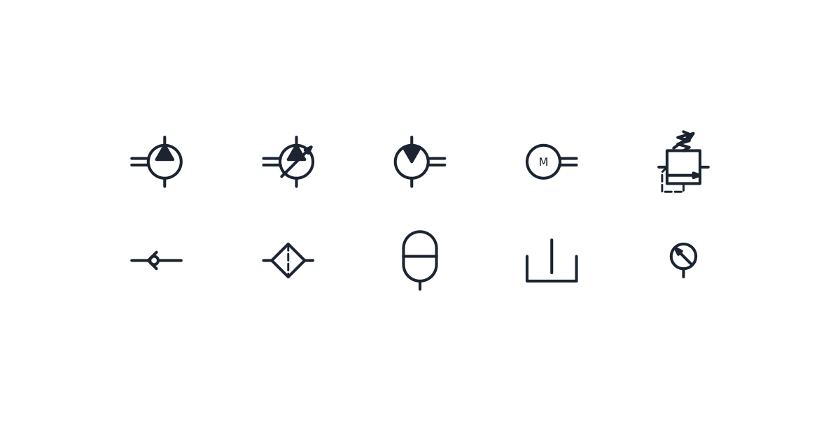
Fixed and variable displacement pumps, the hydraulic motor and the parts of a power unit, drawn to couple shaft to shaft.
Hydraulic pump symbol library
-
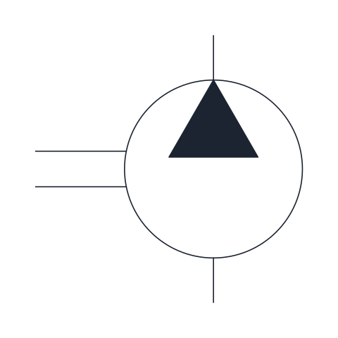
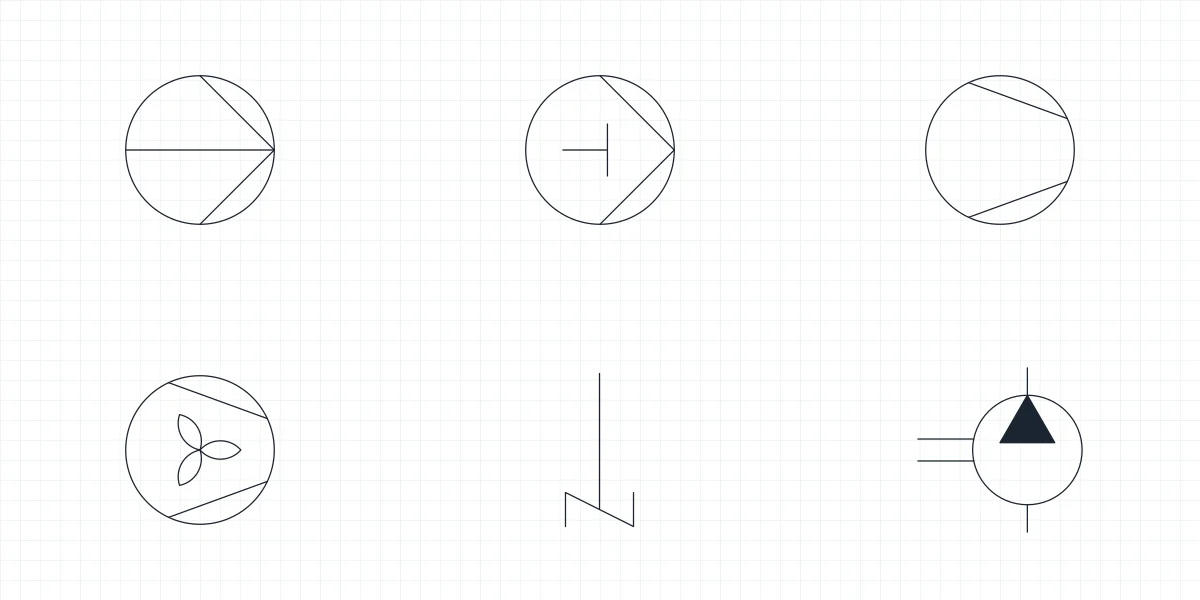
Fixed displacement hydraulic pump
Pump that delivers the same volume per revolution, drawn as a circle with a filled triangle pointing to the outlet and the drive shaft on the side. Use it for the power unit of simple circuits where flow only changes with shaft speed.
IND_HYDRAULIC_SYMBOLS_HYDRAULIC_PUMP_FIXED
-
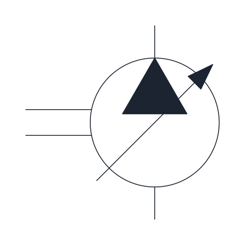
Variable displacement hydraulic pump
Pump whose displacement can be adjusted, shown by the oblique arrow across the circle. It appears in circuits that match flow to demand, such as pressure-compensated or load-sensing systems.
IND_HYDRAULIC_SYMBOLS_HYDRAULIC_PUMP_VARIABLE
-
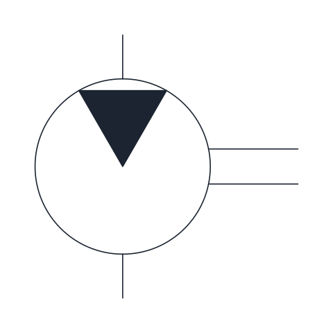
Fixed displacement hydraulic motor
Rotary actuator that turns fluid flow into shaft rotation; the filled triangle points inward at the inlet. Draw it wherever the circuit drives a winch, conveyor or wheel.
IND_HYDRAULIC_SYMBOLS_HYDRAULIC_MOTOR_FIXED
-
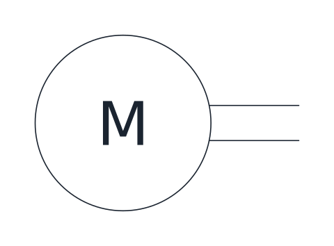
Electric motor (prime mover)
Circle with the letter M and an output shaft, representing the electric motor that drives a pump. Place it next to the pump so the two shafts meet.
IND_HYDRAULIC_SYMBOLS_ELECTRIC_MOTOR_DRIVE
-
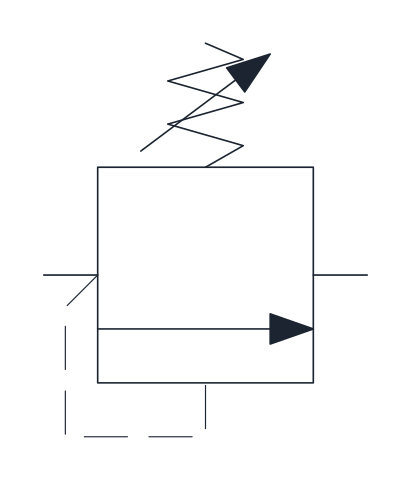
Pressure relief valve
Normally closed valve with an adjustable spring: inlet pressure, sensed through the dashed pilot line, opens the path to tank once it overcomes the spring. It sets the maximum pressure of the circuit.
IND_HYDRAULIC_SYMBOLS_PRESSURE_RELIEF_VALVE
-
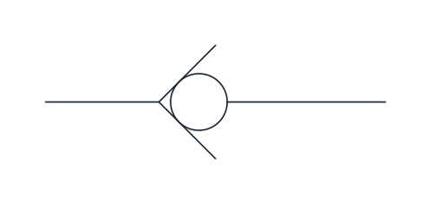
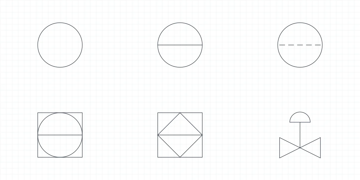
Check valve
Ball pressed against a seat that lets flow pass from left to right and blocks the reverse direction. Draw it wherever the circuit must stop back-flow, for example at a pump outlet.
IND_HYDRAULIC_SYMBOLS_CHECK_VALVE
-
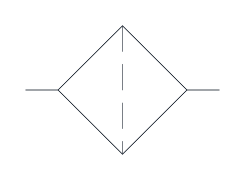
Filter
Square set on its corner with the dashed filter element across the flow path. Place it in the suction, pressure or return line depending on what it protects.
IND_HYDRAULIC_SYMBOLS_FILTER
-
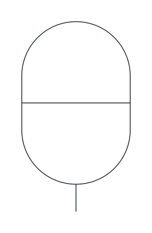
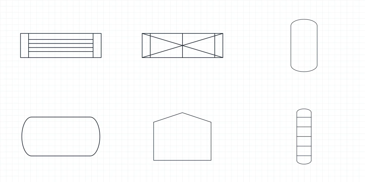
Gas-loaded accumulator
Vertical capsule divided by a separating element, storing fluid under pressure against a gas charge. Used for energy storage, pulsation damping and emergency supply.
IND_HYDRAULIC_SYMBOLS_ACCUMULATOR
-
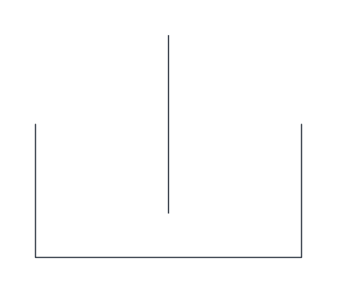
Reservoir (tank)
Open-top tank vented to atmosphere, with the line ending below the fluid level. Each return or drain line in a circuit ends at one of these symbols.
IND_HYDRAULIC_SYMBOLS_RESERVOIR
-
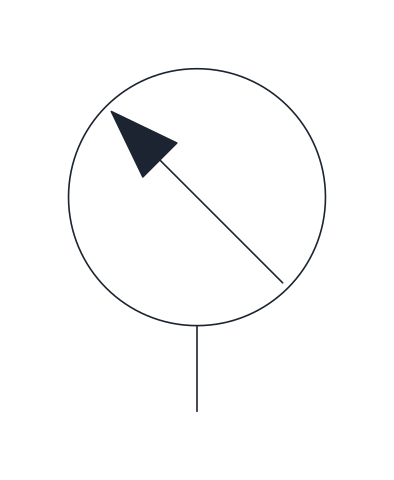
Pressure gauge
Measuring instrument circle with an oblique pointer arrow, connected to the line whose pressure it shows. Draw it at test points and after pressure control valves.
IND_HYDRAULIC_SYMBOLS_PRESSURE_GAUGE
- Units
- Millimetres (INSUNITS 4), drawn at paper size
- Formats
- DWG 2010 · DXF R2010 · PDF
- Opens in
- AutoCAD and AutoCAD LT 2010 or later, BricsCAD, ZWCAD and DraftSight. The DXF opens in most CAD programs.
- Views
- Sheet
- License
- Free for personal and commercial projects. License
This download gives you the hydraulic pump symbol in its fixed and variable displacement forms, the fixed displacement hydraulic motor and the parts that usually sit around a pump in a power unit: electric motor drive, pressure relief valve, check valve, filter, accumulator, reservoir and pressure gauge. That makes 10 named blocks in DWG and DXF, with a PDF sheet that prints them all. Block names match the full library, for example IND_HYDRAULIC_SYMBOLS_HYDRAULIC_PUMP_FIXED.
Reading the hydraulic pump symbol
The pump is a 10 mm circle with a filled triangle at the outlet, pointing outward, because energy leaves the pump through the fluid. Suction is at the bottom and delivery at the top. The drive shaft is the double line on the left side. The base point sits on the free end of the suction connection, so the block drops straight onto a line coming up from the tank.
The fixed displacement pump delivers the same volume on every revolution, and its flow only changes with shaft speed. It fits simple circuits and the tandem-centre valves that unload it to tank.
Variable displacement pump symbol
An oblique arrow drawn across the circle turns the fixed pump into the variable displacement pump. Draw it where the circuit matches flow to demand, as in pressure-compensated or load-sensing systems. The circle, ports and base point are the same as in the fixed version, so you can swap one block for the other without moving any line.
Hydraulic motor symbol compared with the pump
The hydraulic motor uses the same circle, but the filled triangle sits at the inlet on top and points inward, toward the centre, because energy enters the motor. Its shaft leaves on the right. Use it for a winch, a conveyor or a wheel drive. A pump and a motor drawn next to each other differ only in the direction of the triangle, so check it before plotting.
Drawing a hydraulic power unit around the pump
The electric motor is a circle with an M, placed by its centre, with its shaft to the right. Put its centre 20 mm left of the pump base point and 7.5 mm up and the two shafts meet. The reservoir has its base point at the top of its single line, which ends below the fluid level. The filter goes in the suction, pressure or return line and is placed by its left connection.
After the pump, the pressure relief valve sets the maximum pressure of the circuit: it stays closed until the inlet pressure, sensed through its dashed pilot line, overcomes the spring. A check valve at the pump outlet stops back-flow. The accumulator, placed by its lower connection, stores fluid under gas pressure, and the 7.5 mm pressure gauge marks test points. From the pump, the line goes on to the directional control valve symbols; for process pumps on a P&ID, see the pump symbol page, and the whole set of fluid power blocks is in the hydraulic symbols library.
Our drawings follow the ISO 1219-1 conventions for fluid power diagrams. The standard is available from ISO and is not reproduced on this page.