Capacitor symbol and component blocks for CAD
Capacitors, resistors, an inductor, a battery cell, a diode and an LED as IEC 60617 CAD blocks.
Capacitor symbol library
-
Capacitor
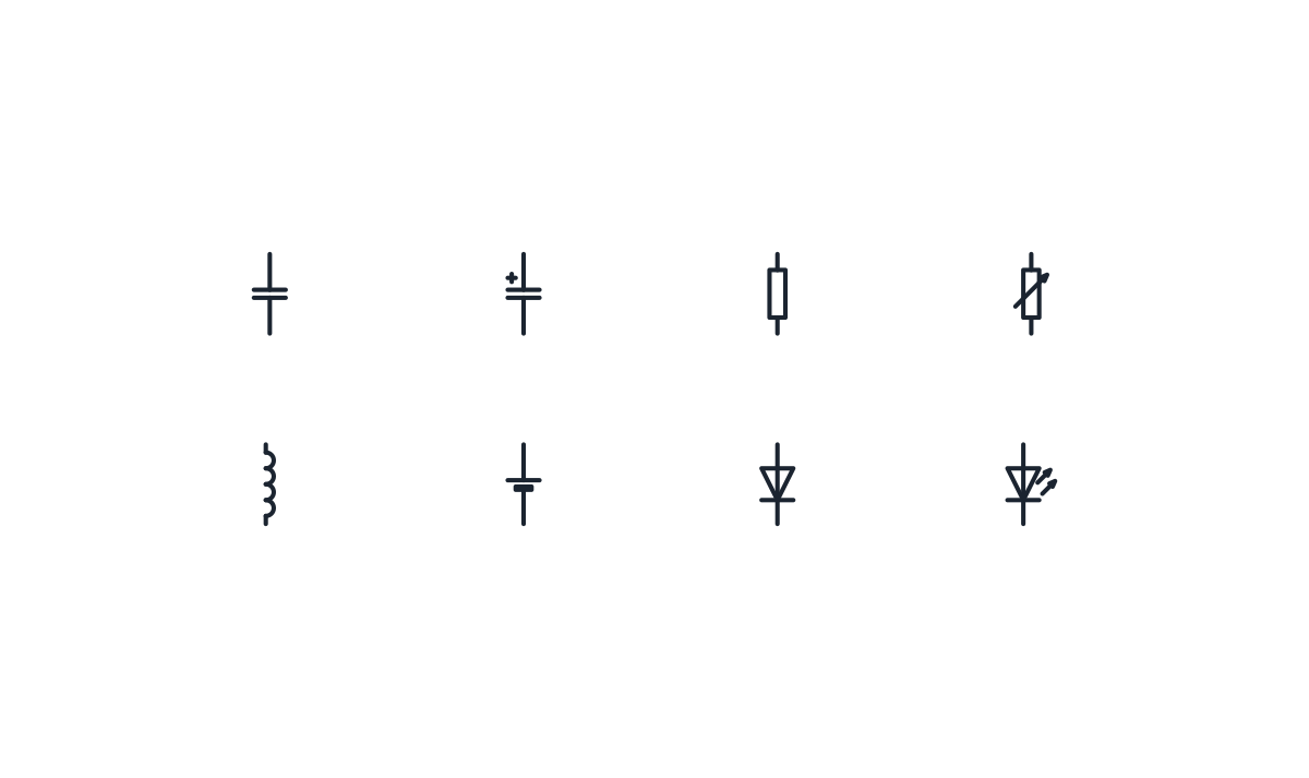
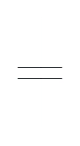
Two parallel plates for a non-polarized capacitor, as used for interference suppression or power factor correction.
IND_ELECTRICAL_SCHEMATIC_SYMBOLS_CAPACITOR
-
Polarized capacitor
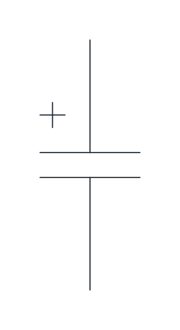
A capacitor with a plus sign at the positive plate, for electrolytic capacitors that must be connected the right way round.
IND_ELECTRICAL_SCHEMATIC_SYMBOLS_POLARISED_CAPACITOR
-
Resistor
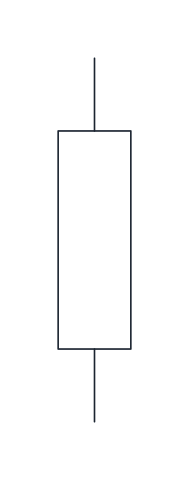
A rectangle with a lead at each end for a fixed resistor.
IND_ELECTRICAL_SCHEMATIC_SYMBOLS_RESISTOR
-
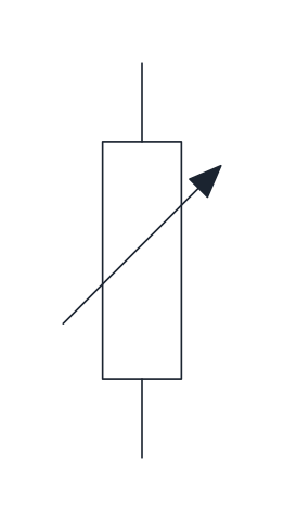
Variable resistor
A resistor crossed by an oblique arrow, showing that its value can be adjusted, as in a rheostat or trimmer.
IND_ELECTRICAL_SCHEMATIC_SYMBOLS_VARIABLE_RESISTOR
-

Inductor
A row of four half loops for a coil or choke whose function is its inductance, such as a line reactor.
IND_ELECTRICAL_SCHEMATIC_SYMBOLS_INDUCTOR
-
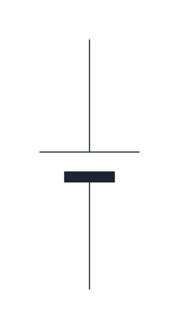
Battery cell
A long thin plate for the positive pole and a short thick plate for the negative pole of a single cell. Repeat it for a multi-cell battery.
IND_ELECTRICAL_SCHEMATIC_SYMBOLS_BATTERY_CELL
-
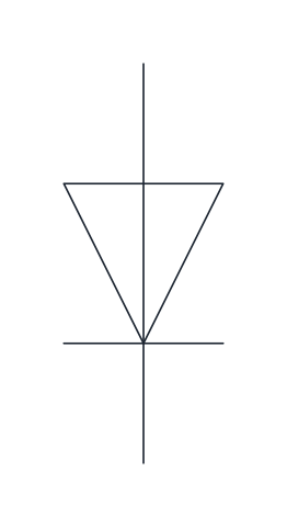
Diode
A triangle and bar showing a semiconductor diode that conducts from anode to cathode, the bar side. Drawn here with the anode at the top.
IND_ELECTRICAL_SCHEMATIC_SYMBOLS_DIODE
-
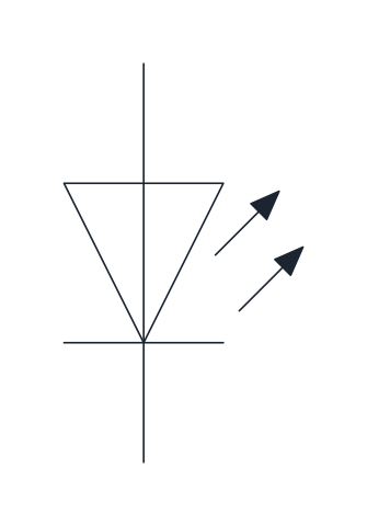
Light-emitting diode (LED)
A diode with two outward arrows that show emitted light, used for indicator LEDs on panels and boards.
IND_ELECTRICAL_SCHEMATIC_SYMBOLS_LED
- Units
- Millimetres (INSUNITS 4), drawn at paper size
- Formats
- DWG 2010 · DXF R2010 · PDF
- Opens in
- AutoCAD and AutoCAD LT 2010 or later, BricsCAD, ZWCAD and DraftSight. The DXF opens in most CAD programs.
- Views
- Sheet
- License
- Free for personal and commercial projects. License
This download holds the capacitor symbol and the other basic components of a schematic: non-polarised and polarised capacitors, fixed and variable resistors, an inductor, a battery cell, a diode and an LED. All eight are drawn after IEC 60617 as named blocks in DWG and DXF, with the same names as the full schematic library, and a PDF sheet shows each one with its name.
Capacitor symbol: non-polarised and polarised
A capacitor is two parallel plates with a lead on each side. The plain version is for non-polarised parts, such as the capacitors used for interference suppression or power factor correction. The polarised version adds a plus sign at the positive plate, for electrolytic capacitors that must be connected the right way round. US schematics often draw the negative plate of a polarised capacitor as a curved line instead, so a curved plate on a drawing means the same thing as the plus sign here.
Resistor symbol: IEC rectangle or US zigzag
The IEC resistor is a plain rectangle with a lead at each end. The zigzag line found on many US drawings is the same component in the American style. A variable resistor, such as a rheostat or a trimmer, adds an oblique arrow across the rectangle. If a project mixes both styles, pick one before you start and keep to it on every sheet.
Diode symbol and LED symbol
The diode is a triangle pointing at a bar. Current flows in the direction the triangle points, from the anode to the cathode on the bar side. In these blocks the anode is at the top, so the diode conducts downwards along a vertical wire. In control circuits a diode is often wired across a DC relay coil, with the cathode towards the positive side, to absorb the voltage spike when the coil is switched off. The coil itself is on the relay symbol page. The LED is the same diode with two arrows pointing out, for indicator lights on panels and boards.
Inductor and battery cell symbols
The inductor is a row of four half loops, for a coil or a choke used for its inductance, such as a line reactor in front of a drive. Do not use it for the coil of a relay, which has its own rectangle. The battery cell has a long thin plate for the positive pole and a short thick plate for the negative pole. A battery with several cells is drawn by repeating the cell.
Using capacitor and component blocks in a schematic
All the components are in-line blocks drawn at paper size on a 2.5 mm grid with the current path vertical. The base point is the lower terminal and the upper terminal is 12.5 mm above it, the same pitch as the contacts and coils of the electrical schematic symbols library. On a horizontal wire, rotate the block 90 degrees about its base point and it stays on the grid.
The component shapes come from IEC 60617. For the official drawings, use the online database that IEC sells by subscription.