Ladder diagram symbols: IEC 61131-3 blocks for CAD
The graphic elements of IEC 61131-3 ladder logic as CAD blocks, from contacts and coils to timers and counters.
Ladder diagram symbols library
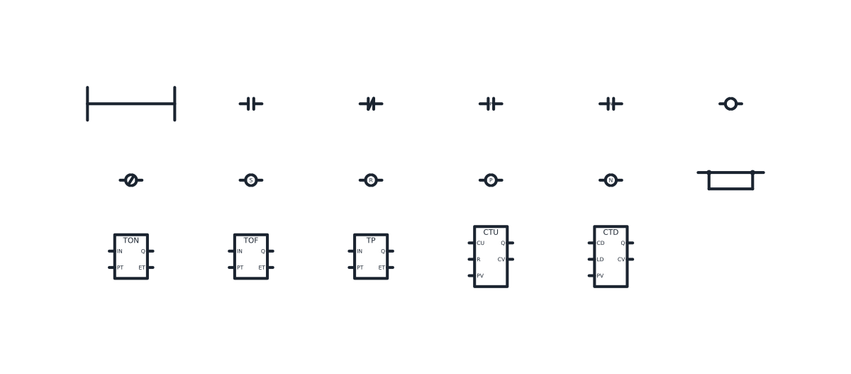
Ladder rungs and branches
-
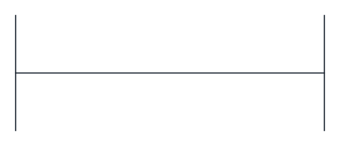
Power rails with an empty rung
The left and right power rails of a ladder diagram joined by one rung, ready to receive contacts on the left and coils on the right.
IND_LADDER_DIAGRAM_SYMBOLS_POWER_RAILS
-
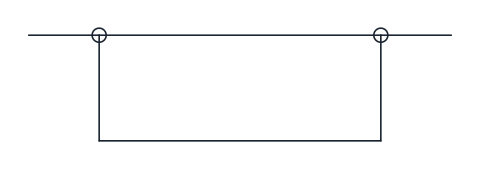
Parallel branch (OR)
Two paths that split from the rung and join again, so power passes if either path conducts.
IND_LADDER_DIAGRAM_SYMBOLS_PARALLEL_BRANCH
Ladder contact symbols
-
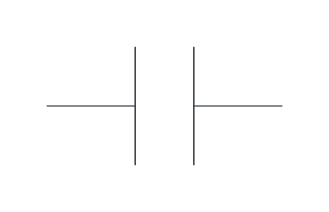
Normally open contact
Passes power along the rung when the associated Boolean variable is on. In IEC 61131-3 ladder it is drawn as two parallel bars.
IND_LADDER_DIAGRAM_SYMBOLS_NO_CONTACT
-
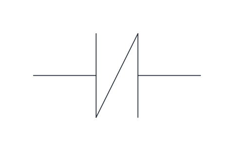
Normally closed contact
Passes power when the associated variable is off, the inverse of the normally open contact. The slash between the bars marks the negation.
IND_LADDER_DIAGRAM_SYMBOLS_NC_CONTACT
-
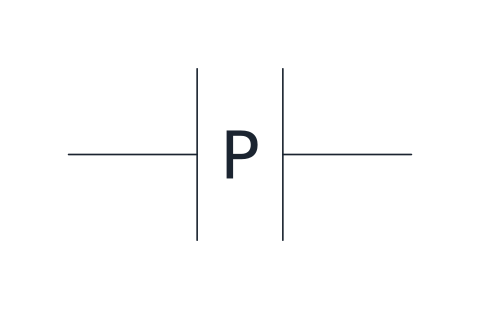
Positive transition-sensing contact
Passes power for one scan when its variable changes from off to on, used to act once on a rising edge.
IND_LADDER_DIAGRAM_SYMBOLS_POSITIVE_TRANSITION_CONTACT
-
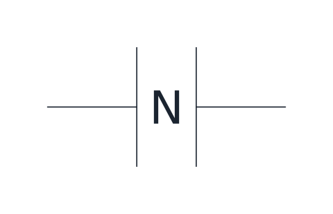
Negative transition-sensing contact
Passes power for one scan when its variable changes from on to off, the falling-edge counterpart.
IND_LADDER_DIAGRAM_SYMBOLS_NEGATIVE_TRANSITION_CONTACT
Ladder coil symbols
-
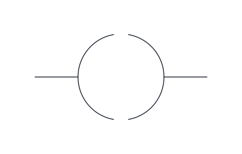
Coil
Writes the state of the rung to its variable: on when power reaches it, off when it does not.
IND_LADDER_DIAGRAM_SYMBOLS_COIL
-
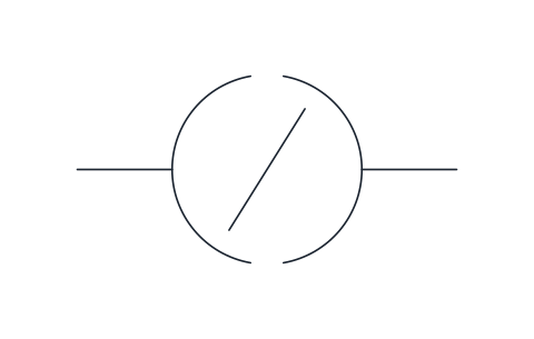
Negated coil
Writes the inverse of the rung state to its variable, so the variable is on while the rung is off.
IND_LADDER_DIAGRAM_SYMBOLS_NEGATED_COIL
-
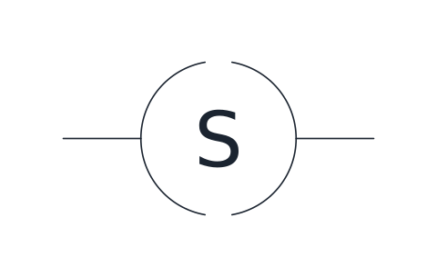
Set coil
Turns its variable on when the rung carries power and leaves it on until a reset coil turns it off.
IND_LADDER_DIAGRAM_SYMBOLS_SET_COIL
-
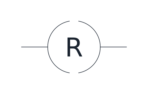
Reset coil
Turns its variable off when the rung carries power, the partner of the set coil.
IND_LADDER_DIAGRAM_SYMBOLS_RESET_COIL
-
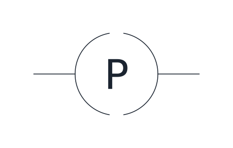
Positive transition-sensing coil
Sets its variable for one scan when the rung goes from off to on.
IND_LADDER_DIAGRAM_SYMBOLS_POSITIVE_TRANSITION_COIL
-
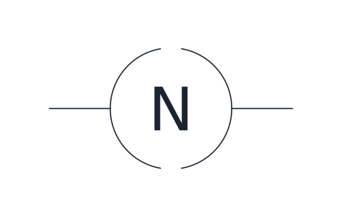
Negative transition-sensing coil
Sets its variable for one scan when the rung goes from on to off.
IND_LADDER_DIAGRAM_SYMBOLS_NEGATIVE_TRANSITION_COIL
PLC timer and counter symbols
-
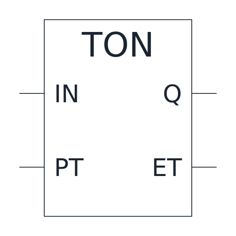
On-delay timer (TON)
Sets output Q once input IN has stayed on for the preset time PT; ET shows the elapsed time.
IND_LADDER_DIAGRAM_SYMBOLS_TIMER_ON_DELAY_TON
-
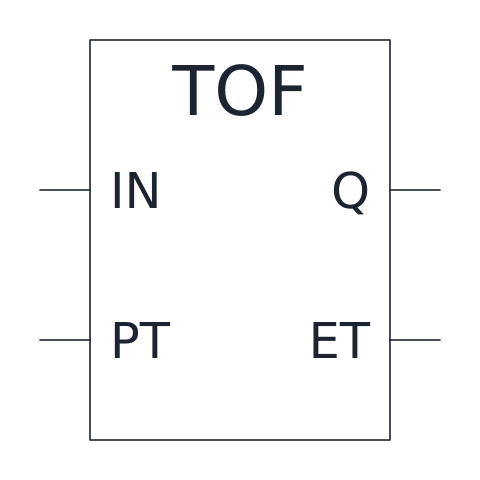
Off-delay timer (TOF)
Keeps output Q on for the preset time PT after input IN turns off.
IND_LADDER_DIAGRAM_SYMBOLS_TIMER_OFF_DELAY_TOF
-
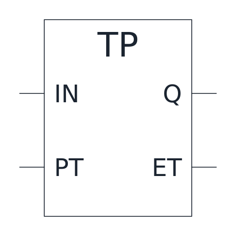
Pulse timer (TP)
Gives a pulse of fixed length PT on output Q each time input IN turns on.
IND_LADDER_DIAGRAM_SYMBOLS_PULSE_TIMER_TP
-
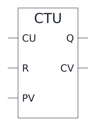
Up counter (CTU)
Counts rising edges on CU, sets Q when the count CV reaches the preset PV and clears on R.
IND_LADDER_DIAGRAM_SYMBOLS_COUNTER_UP_CTU
-
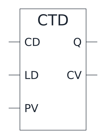
Down counter (CTD)
Counts down on CD from the value loaded with LD and sets Q when the count reaches zero.
IND_LADDER_DIAGRAM_SYMBOLS_COUNTER_DOWN_CTD
- Units
- Millimetres (INSUNITS 4), drawn at paper size
- Formats
- DWG 2010 · DXF R2010 · PDF
- Opens in
- AutoCAD and AutoCAD LT 2010 or later, BricsCAD, ZWCAD and DraftSight. The DXF opens in most CAD programs.
- Views
- Sheet
- License
- Free for personal and commercial projects. License
This download holds seventeen ladder diagram symbols, the graphic elements of the LD language of IEC 61131-3: power rails with a rung, a parallel branch, four contacts, six coils and the standard timers and counters TON, TOF, TP, CTU and CTD. They are named blocks in DWG and DXF, called IND_LADDER_DIAGRAM_SYMBOLS followed by the symbol key, plus a PDF sheet.
Ladder diagram symbols in IEC 61131-3
A ladder diagram draws a PLC program as if it were a relay circuit. Each rung between the two power rails carries conditions on the left and an action on the right. The look comes from relay schematics, but a contact here reads a variable in PLC memory, not a physical contact. The blocks serve manuals, specifications and training sheets drawn in CAD. Relay circuits in their own symbols are on the electrical schematic symbols page.
Ladder logic contacts: normally open, normally closed and edges
The normally open contact, two parallel bars, passes power when its variable is on. The normally closed contact adds a slash between the bars and passes power when the variable is off. The P and N contacts pass power for one scan only, when the variable changes from off to on or from on to off. A common trap comes from the field wiring. A push button used as a stop is wired normally closed, so its PLC input is on while nobody touches it. In the program it is read with a normally open contact, which opens the rung when the button is pressed or the wire breaks.
Ladder logic coils: normal, negated, set and reset
A coil, drawn between two arcs, writes the state of the rung to its variable. The negated coil writes the opposite. The S coil turns its variable on and leaves it on, and the R coil turns it off, so a set and reset pair works like a latching relay. P and N coils act for one scan on an edge.
PLC timer and counter blocks
Timers and counters are function blocks with inputs on the left and outputs on the right. TON sets Q once IN has stayed on for the preset time PT, and ET shows the time elapsed. TOF keeps Q on for PT after IN turns off. TP gives a pulse of length PT each time IN turns on. CTU counts rising edges on CU, sets Q when the count CV reaches PV and clears on R. CTD counts down on CD from the value loaded with LD. Each timer or counter is an instance named above the box, for example T1.
Drawing a rung with the ladder diagram blocks
Everything sits on a 2.5 mm grid. Contacts and coils are 10 mm long, with the base point at their left end on the rung, so they chain end to end. The function blocks have their base point at the end of the first input pin, with the pins 7.5 mm apart. The power rails block spans a 40 mm rung, and the parallel branch opens a second path 7.5 mm below the first.
The graphic elements follow the LD language of IEC 61131-3, a standard that IEC publishes and sells. Some PLC vendors draw a few elements in their own style.