Control Valve CAD Block
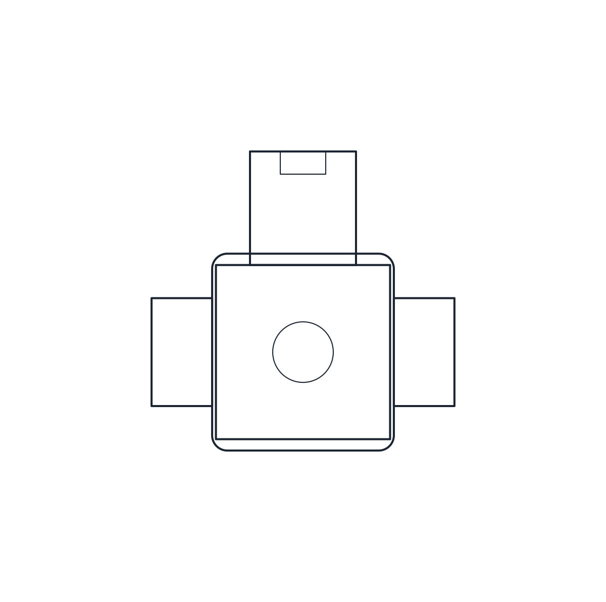
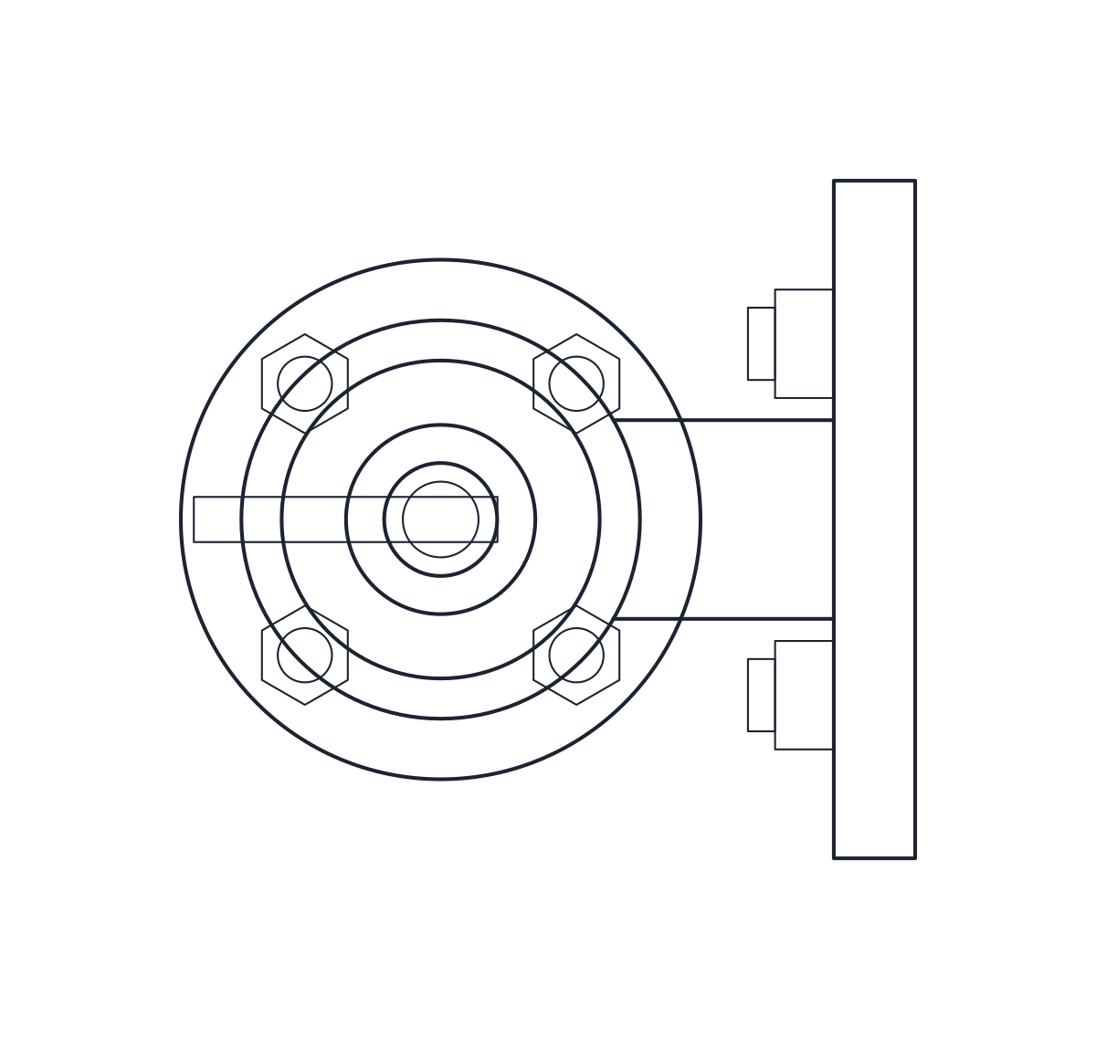
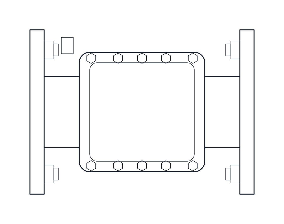
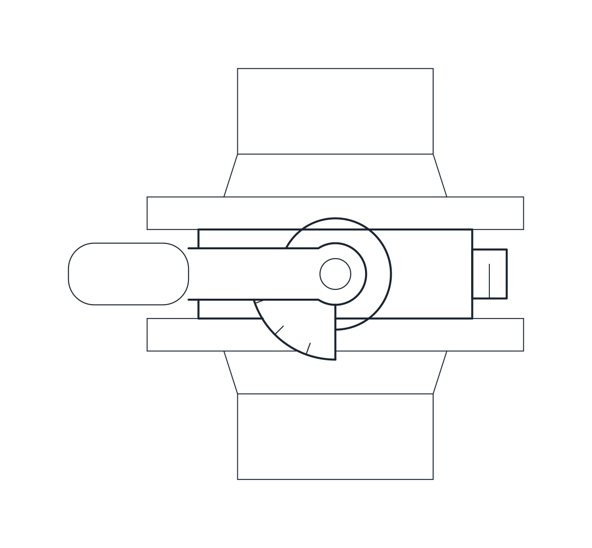
Pneumatic globe control valves in DN50 and DN100, 230 and 350 mm face to face and 387.5 and 708 mm high.
Control valve DN50 PN16 with pneumatic diaphragm actuator
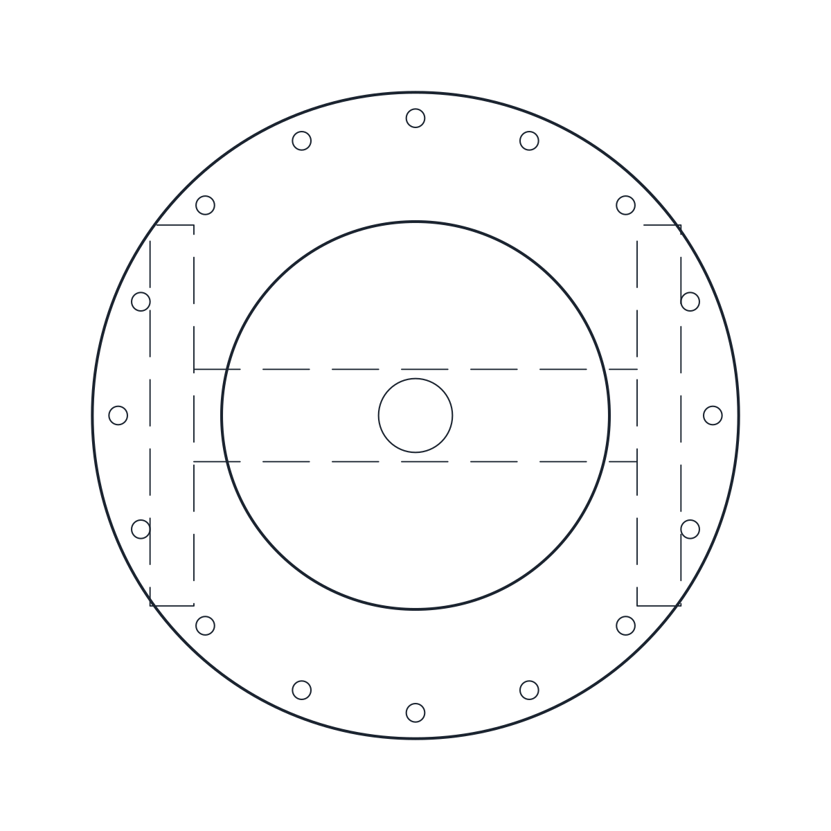
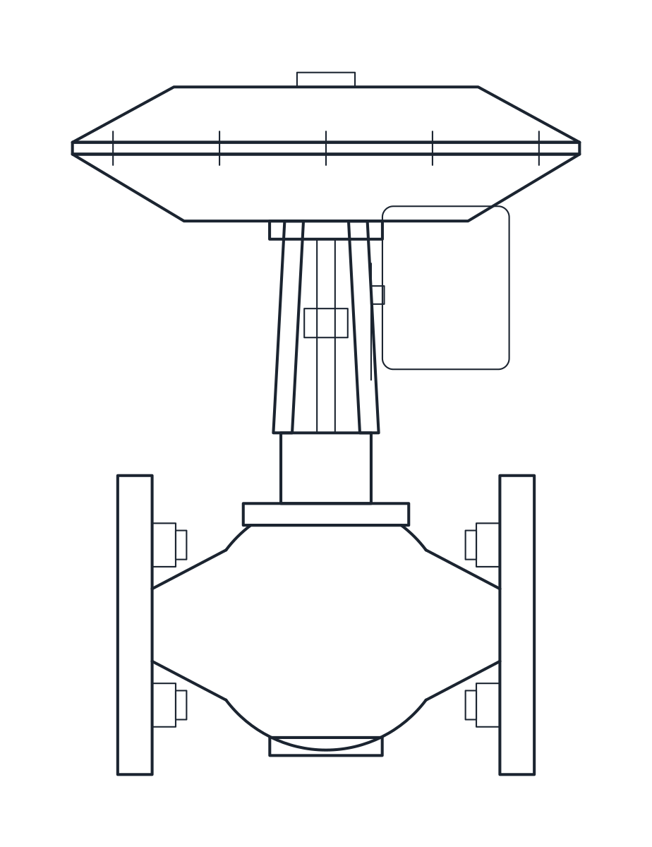
Control valve DN100 PN16 with pneumatic diaphragm actuator
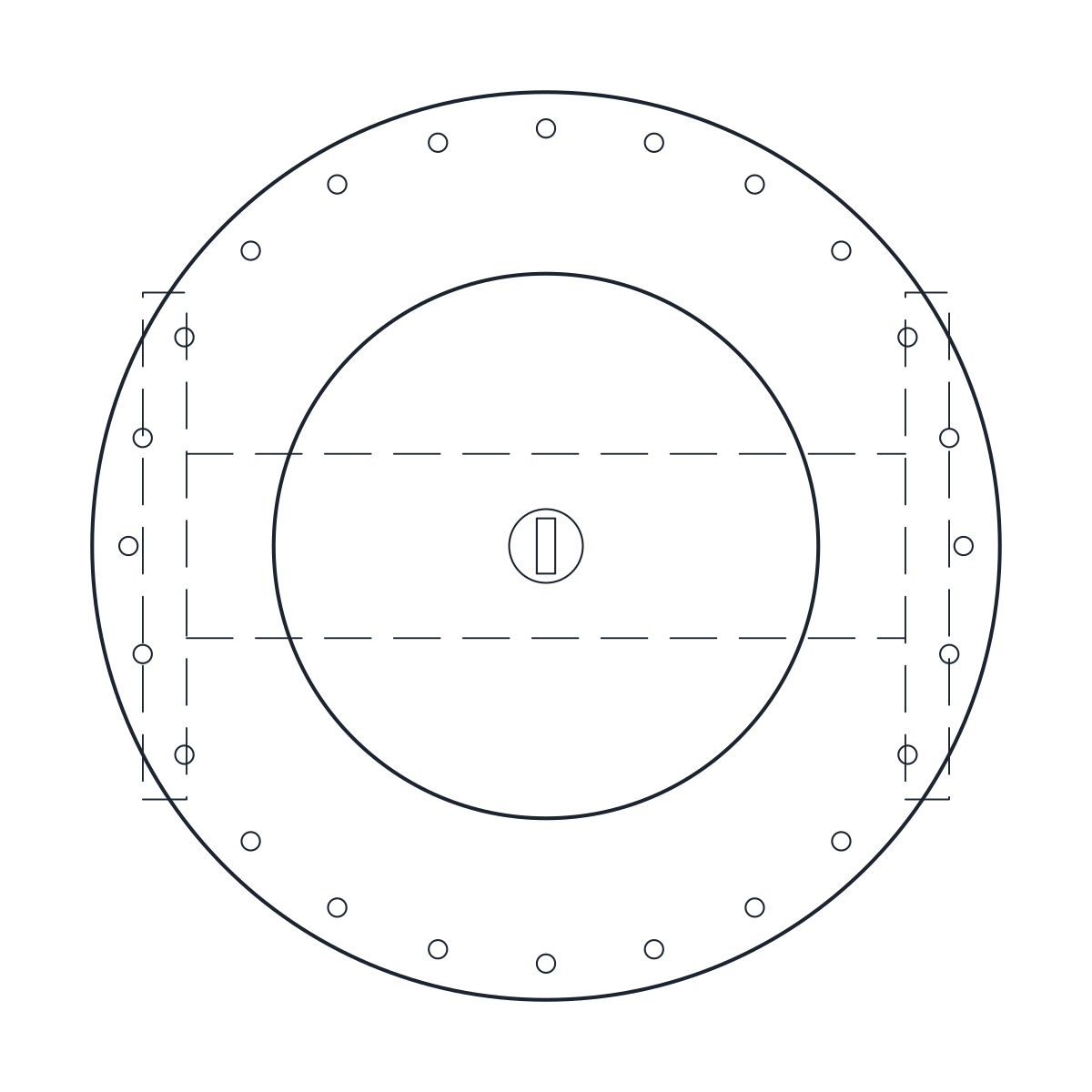
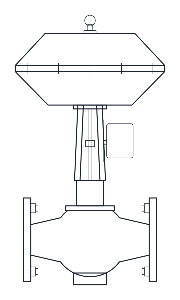
- Units
- Millimetres (INSUNITS 4), drawn at paper size
- Formats
- DWG 2010 · DXF R2010
- Opens in
- AutoCAD and AutoCAD LT 2010 or later, BricsCAD, ZWCAD and DraftSight. The DXF opens in most CAD programs.
- Views
- Plan view + Front elevation
- License
- Free for personal and commercial projects. License
This download holds two flanged PN16 globe control valves, DN50 and DN100, each with a yoke and a spring-diaphragm pneumatic actuator. Each size comes as a plan block and an elevation block in millimetres at full size, in a DWG for AutoCAD 2010 and later and in a DXF.
Control valve DWG dimensions
The measurements come from a typical catalogue valve and actuator, so check them against the datasheet of the valve you will order.
- DN50: 230 mm face to face, 223 mm from the pipe axis to the actuator yoke, 72 mm from the axis to the bottom of the body, 165 mm flanges.
- DN100: 350 mm face to face, 354 mm from the axis to the yoke, 118 mm from the axis to the bottom, 220 mm flanges.
The DN50 valve carries a 350 cm2 actuator with a 280 mm diaphragm case, 82 mm high. The DN100 valve carries a 750 cm2 actuator with a 394 mm case, 236 mm high including the lifting eyelet. These pairings are typical for each size but not the only ones, since the actuator depends on the travel and the forces of your process. The positioner on the side of the yoke is a representative box.
Control valve drawing in plan and elevation
The elevation shows the globe body between the flanges, the yoke and the stem, and the actuator case on top. The overall blocks are 280 x 280 x 387.5 mm for DN50 and 394 x 394 x 708 mm for DN100. In plan the round diaphragm case covers the whole valve, so the plan is a circle with the flanges seen through it as hidden lines on layer A-HIDN.
Using the control valve block in a valve station
A control valve is often mounted with isolating valves on each side and a bypass. The face-to-face lengths match the globe valve block at the same DN, which keeps the station symmetrical when you draw a manual bypass valve. Leave room above the actuator to lift it off the yoke. On a P&ID the actuator goes on a stem over the body, as shown with the valve symbols, and the loop around it uses the instrumentation symbols.