Ball Valve CAD Block
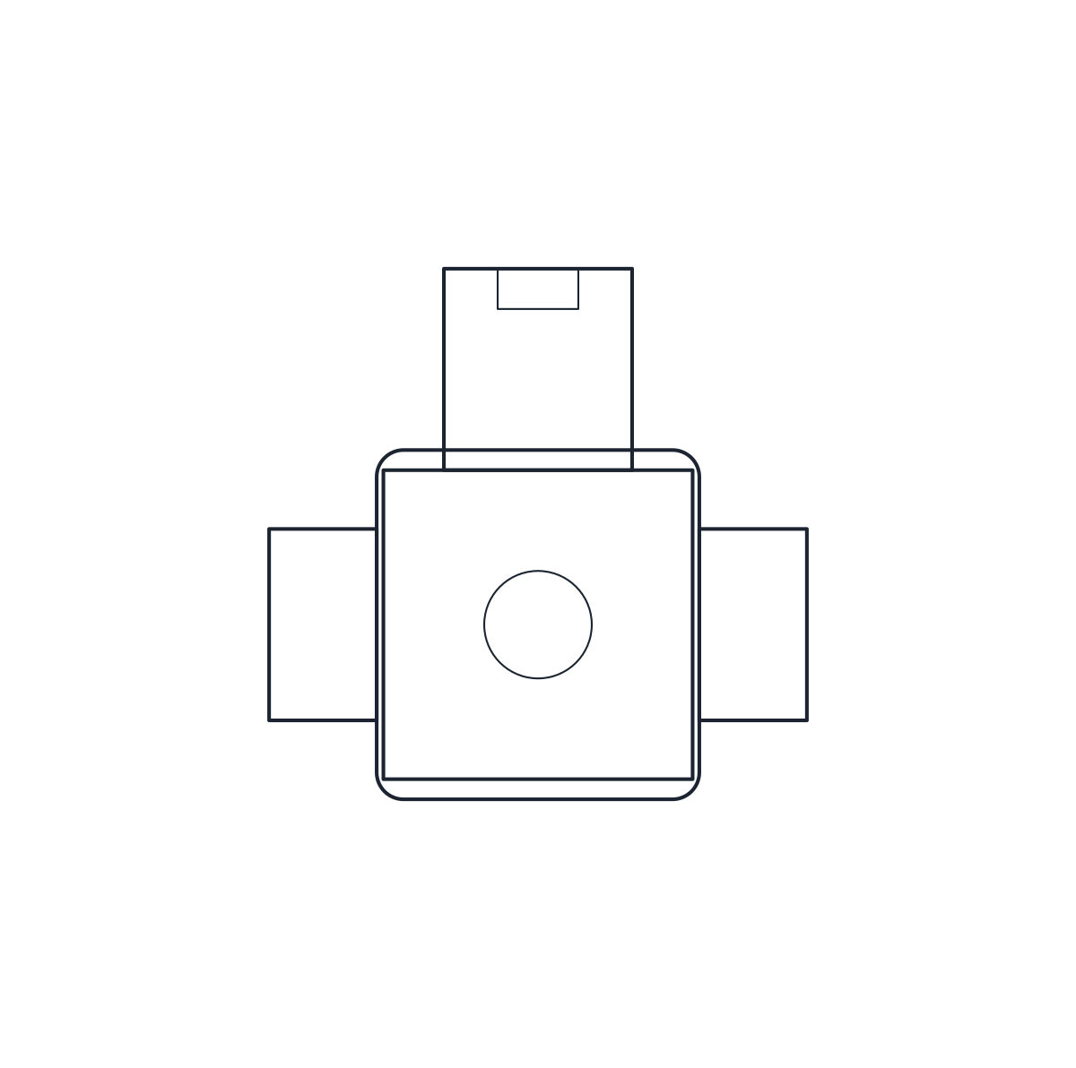
Lever ball valves: DN25 threaded, 85 mm long, and DN50 and DN100 flanged, 150 and 190 mm face to face.
Ball valve DN25 (G 1), female threaded, lever
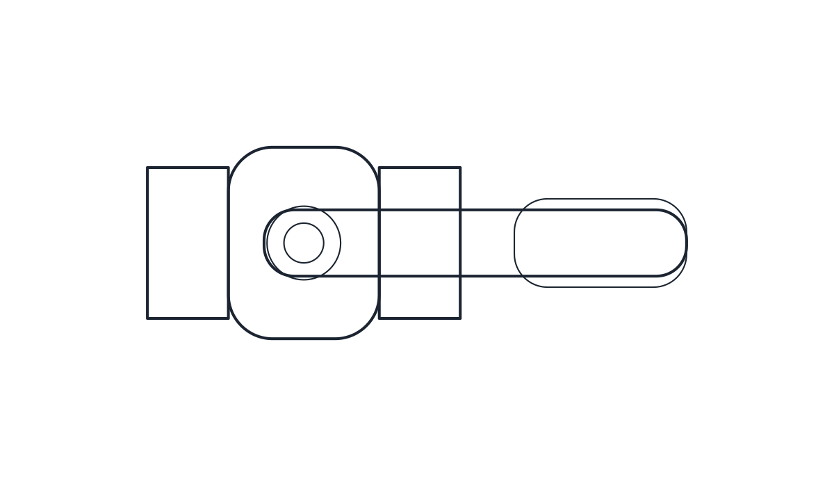
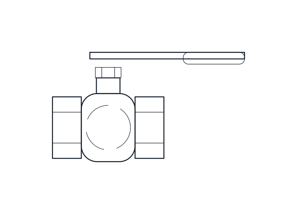
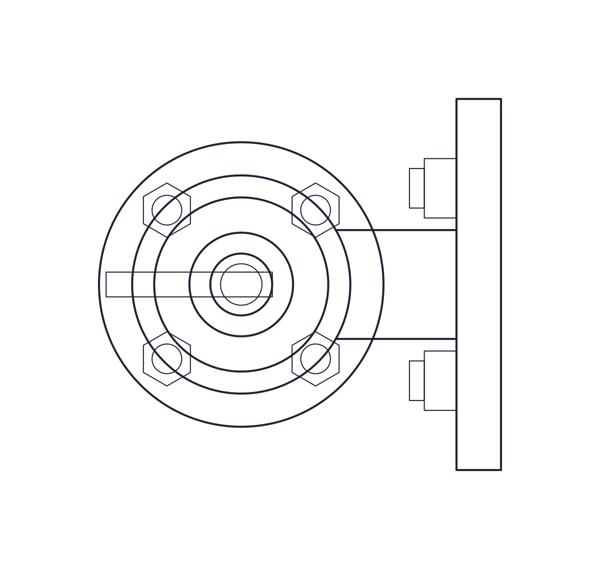
Ball valve DN50 PN16, flanged, lever
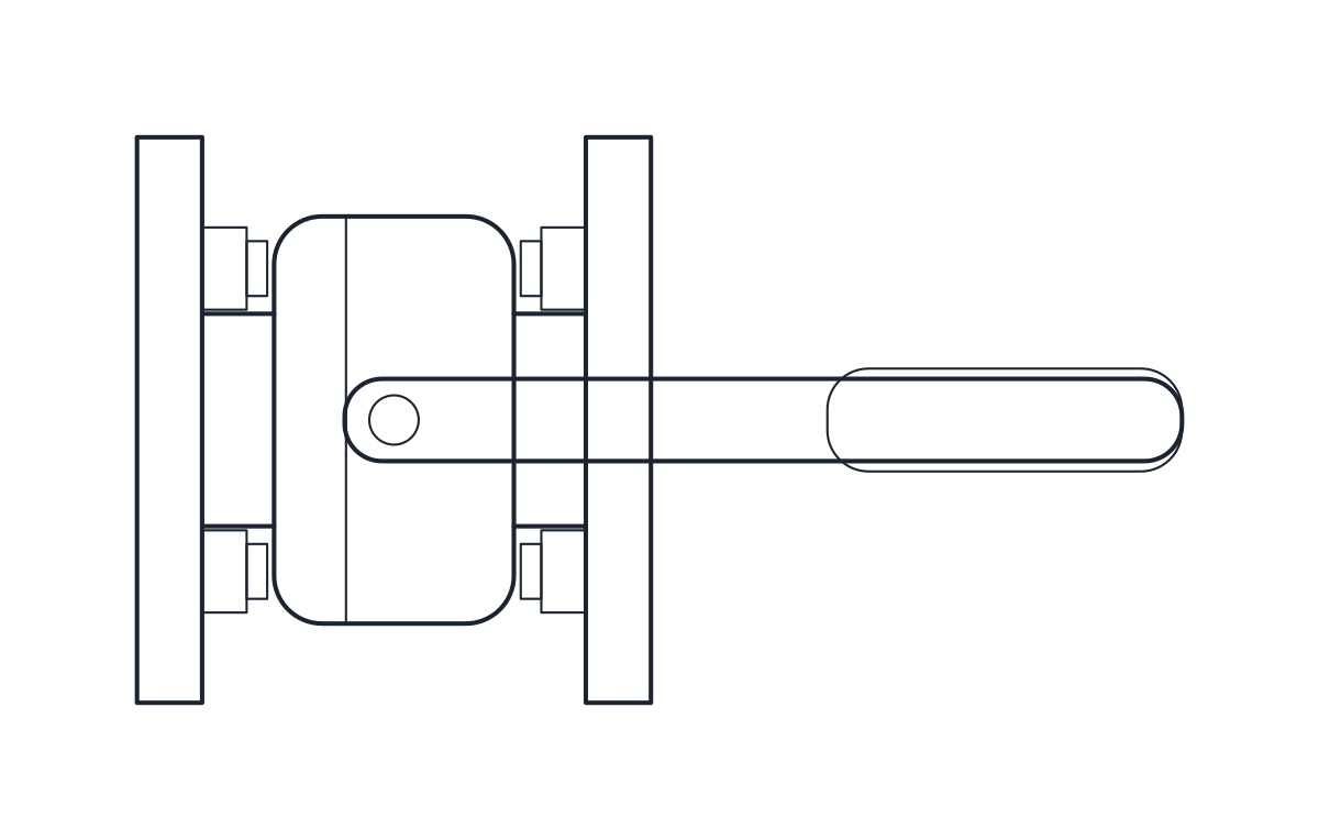
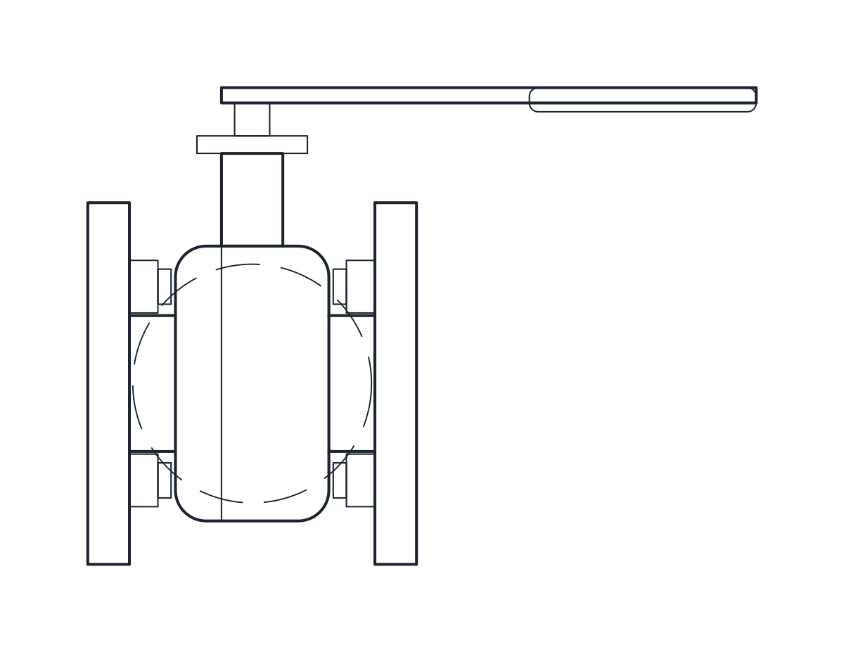
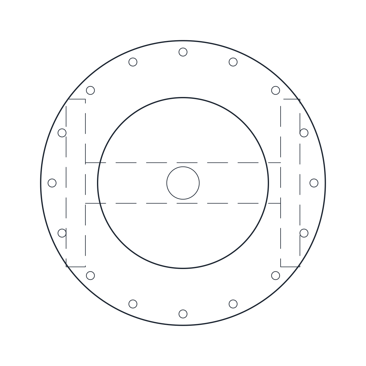
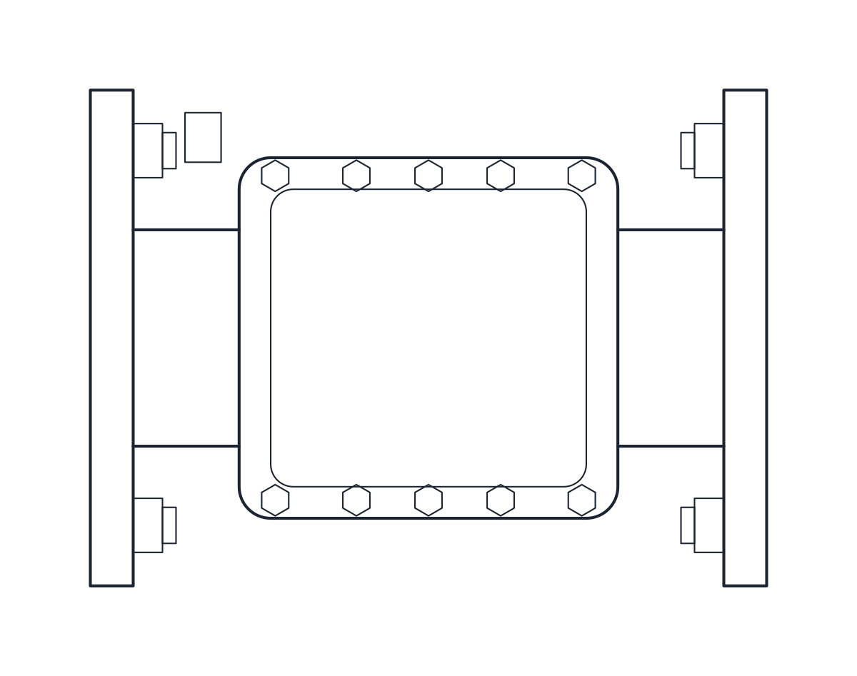
Ball valve DN100 PN16, flanged, lever
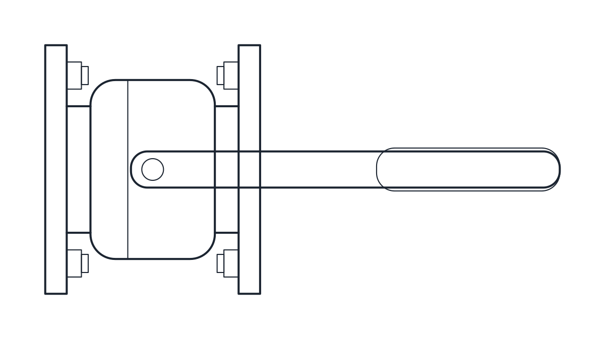
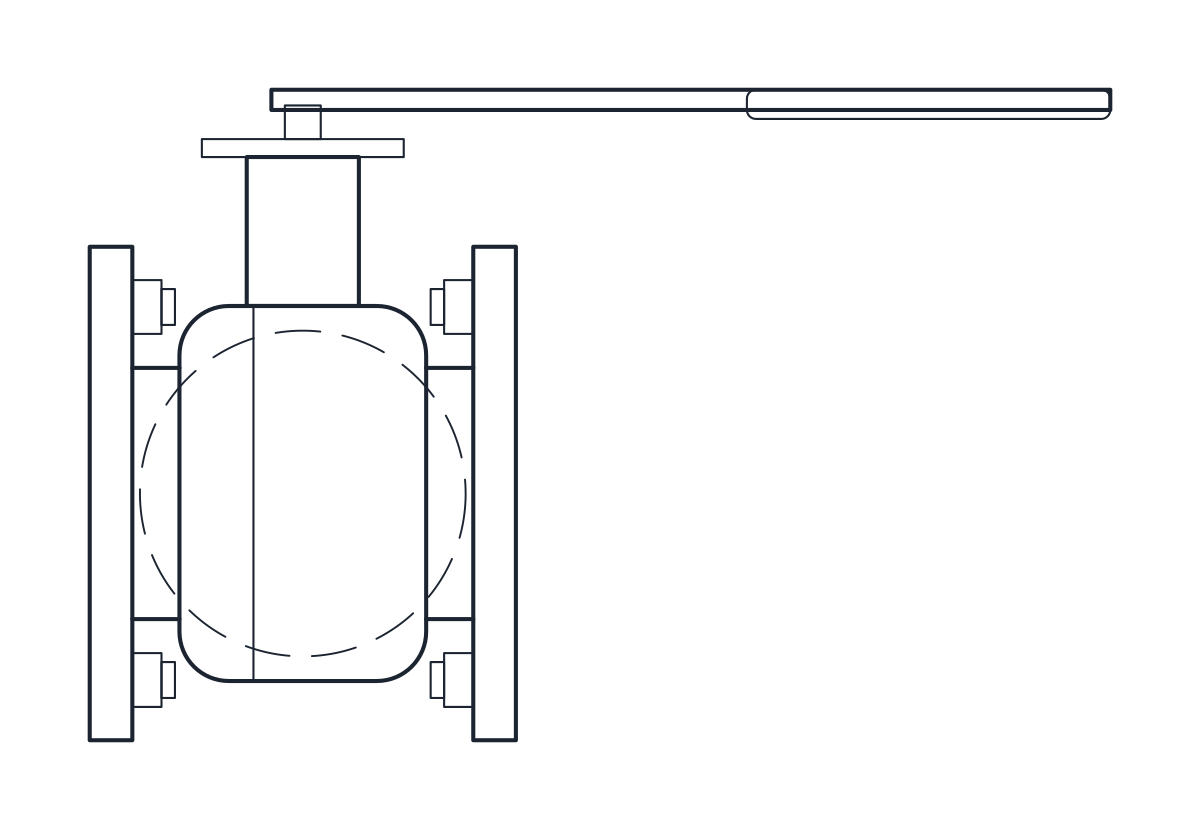
- Units
- Millimetres (INSUNITS 4), drawn at paper size
- Formats
- DWG 2010 · DXF R2010
- Opens in
- AutoCAD and AutoCAD LT 2010 or later, BricsCAD, ZWCAD and DraftSight. The DXF opens in most CAD programs.
- Views
- Plan view + Front elevation
- License
- Free for personal and commercial projects. License
This download holds three lever-operated ball valves: a DN25 valve with G 1 female threads and two flanged PN16 valves, DN50 and DN100. Each comes as a plan block and an elevation block in millimetres at full size. The DWG is saved for AutoCAD 2010 and later, and the DXF works in any CAD program.
Ball valve DWG dimensions
All three are two-piece valves taken from a typical catalogue range. Check the measurements against the datasheet of the valve you will install.
- DN25 threaded, brass body: 85 mm end to end, 104 mm lever, 57.5 mm from the pipe axis to the top of the lever.
- DN50 flanged, ductile iron body: 150 mm face to face, 230 mm lever, 135 mm from the axis to the lever top, 165 mm flanges with 4 x M16.
- DN100 flanged, ductile iron body: 190 mm face to face, 360 mm lever, 180 mm from the axis to the lever top, 220 mm flanges with 8 x M16.
The flanged valves follow EN 558 series 14 for face-to-face length and EN 1092 PN16 for the flanges. The lever length is read from the stem axis.
Ball valve drawing in plan and elevation
The valves are drawn open, with the lever parallel to the pipe. The ball is a hidden circle on layer A-HIDN. Because the lever is longer than half the valve, it sticks out past the end of the body, and the blocks are wider than the face-to-face length: 146.5 mm for DN25, 305 mm for DN50 and 455 mm for DN100. Keep that in mind when you place two valves close together or next to a wall.
Using the ball valve block in a piping layout
Turning the valve shut swings the lever through a quarter turn, so leave a clear arc around the stem in plan. If you need the lever on the other side, mirror the block about the pipe axis. The body is on layer M-VALV and bolts and lever details on M-VALV-DETL. For a larger quarter-turn valve with a short body, see the butterfly valve block. On a P&ID the ball valve is a symbol among the valve symbols.