Heat Exchanger CAD Block
A three-pass shell-and-tube oil cooler, 1078 mm long, Ø178 shell, feet at 560 mm centres.
Small shell-and-tube heat exchanger, 1078 long, Ø178 shell, three-pass water
- Units
- Millimetres (INSUNITS 4), drawn at paper size
- Formats
- DWG 2010 · DXF R2010
- Opens in
- AutoCAD and AutoCAD LT 2010 or later, BricsCAD, ZWCAD and DraftSight. The DXF opens in most CAD programs.
- Views
- Plan view + Front elevation
- License
- Free for personal and commercial projects. License
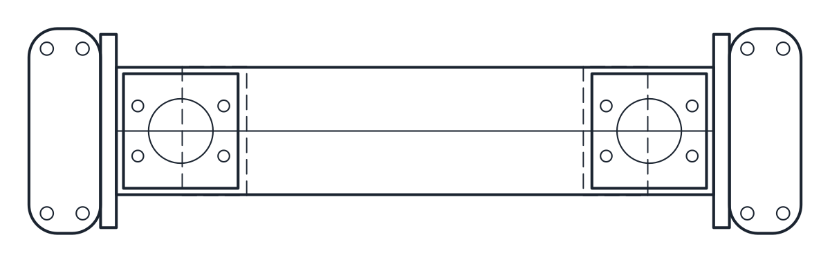
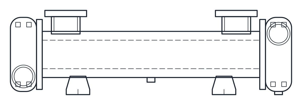
This heat exchanger CAD block download holds one small shell-and-tube heat exchanger, a three-pass oil cooler with water connections on the end covers, drawn in plan and elevation in millimetres in the DWG and DXF. It is 1078 mm long with a Ø178 shell.
Heat exchanger CAD block dimensions
The dimensions come from the data sheet of a typical catalogue three-pass shell-and-tube oil cooler for hydraulic systems. The overall length is 1078 mm, the oil connections are 654 mm apart, the mounting feet are 560 mm apart and the shell is Ø178 mm. The end covers are 286 mm wide and carry 3 in BSP water connections, with the inlet low on one end and the outlet high on the other. The oil ports are SAE 3 in flanges, 160 mm square. Coolers of this type come in many sizes, so take the block as one size and check the sheet of the cooler you select.
Shell and tube heat exchanger drawing in plan and elevation
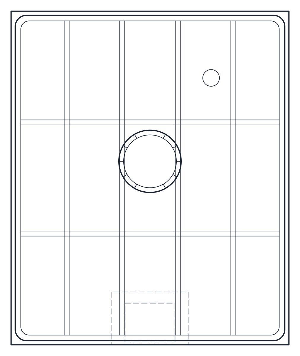
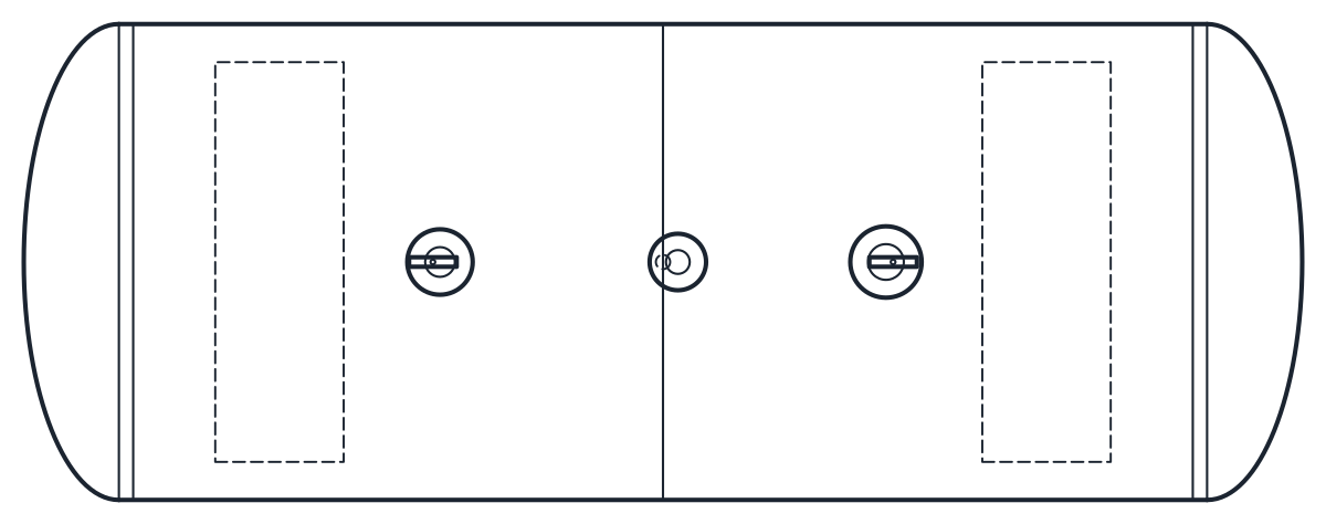
The plan shows the shell, the two end covers and the oil flanges from above, and measures 1078 x 286 mm. The elevation shows the shell on its two feet, the end covers with the water connections and the oil flanges on top. The shell axis sits 155 mm above the mounting face and the top of the oil flanges is at 325 mm, both read from the end view of the same data sheet. The length of each end cover and the shape of the feet are drawn by us and are representative.
Outlines are on layer M-TANK, connections and feet on M-TANK-DETL, and hidden lines on A-HIDN.
Using the heat exchanger block in a hydraulic power unit
Use the 560 mm foot centres to mark the bolts on the frame of the power unit. The oil lines connect to the flanges on top and the cooling water to the end covers, so leave room at both ends for the water pipes and for removing the covers during cleaning. The 654 mm between the oil connections helps to route the return line from the tank.
On the circuit diagram the cooler is drawn with its own symbol, which you will find on the heat exchanger symbol page. For a vessel on the same compressed air or oil system, see the pressure vessel CAD block.