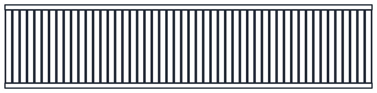
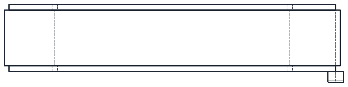
Bucket Elevator CAD Block
A belt bucket elevator 12000 mm high, with a 750 mm boot, 1950 mm leg sections and a 1090 mm wide head.
Belt bucket elevator, 12 m overall height, head, legs and boot

- Units
- Millimetres (INSUNITS 4), drawn at paper size
- Formats
- DWG 2010 · DXF R2010
- Opens in
- AutoCAD and AutoCAD LT 2010 or later, BricsCAD, ZWCAD and DraftSight. The DXF opens in most CAD programs.
- Views
- Plan view + Front elevation
- License
- Free for personal and commercial projects. License
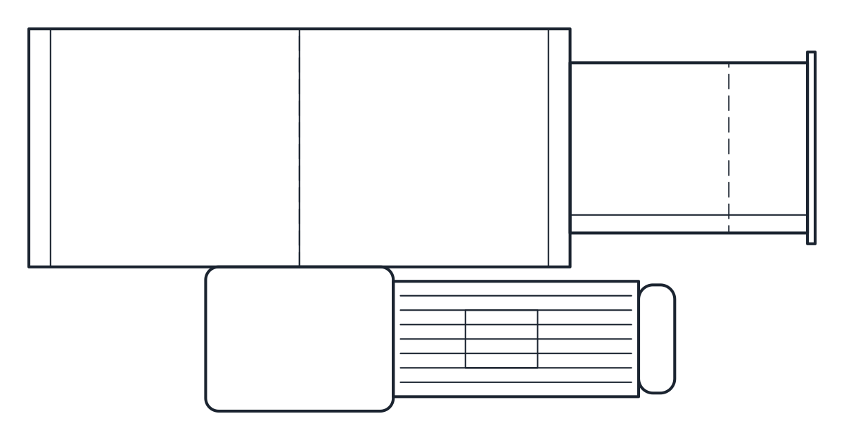
This bucket elevator CAD block download holds one belt bucket elevator with a 12 m overall height, drawn in plan and elevation in millimetres in the DWG and DXF. The drawing shows the boot, the leg sections and the head with its discharge spout and drive.
Bucket elevator CAD block dimensions
The elevator is for grain-like bulk materials and uses the section sizes of a manufacturer's mid model. The boot is 685 mm high and 750 mm wide, the leg sections are 1950 mm long, and the head is 775 mm high and 1090 mm wide including the discharge spout. The casing depth of 330 mm comes from the boot dimension in the datasheet.
The 12000 mm overall height adds up as follows: 106 mm boot feet, the 685 mm boot, five 1950 mm leg sections, one 684 mm make-up section and the 775 mm head. The make-up section is there to reach a round 12 m, and its length is indicative. Check section lengths and the head with your supplier, because the height of a real elevator is set by the plant.
Bucket elevator drawing in plan and elevation
The two leg trunks, the up leg and the down leg, are 210 mm wide and stand side by side with 330 mm between them, which matches the 750 mm boot width. The boot carries the take-up bearing, an inspection door and a 45 degree inlet chute. The head has a round hood split at shaft level, a 45 degree discharge spout and a shaft-mounted gearmotor on the front face. The hood shape, the chutes, the take-up, the doors and the gearmotor are representative.
Bucket size and spacing are not drawn, because they change with the belt and the product. The plan is 1090 x 530 mm. Outlines are on layer M-CONV, details on M-CONV-DETL and hidden lines on A-HIDN.
Using the bucket elevator block in a bulk handling layout
The elevation is tall and narrow, so place it on its own on the sheet or cut it with a break line through the leg sections. In plan, turn the block so that the discharge spout points at the bin or conveyor it feeds and the inlet chute faces the feed. Leave access around the boot, since the take-up and the inspection door are there.
The drive motor appears on the schematic with the motor symbol. To feed the boot from a silo, see the screw conveyor CAD block.