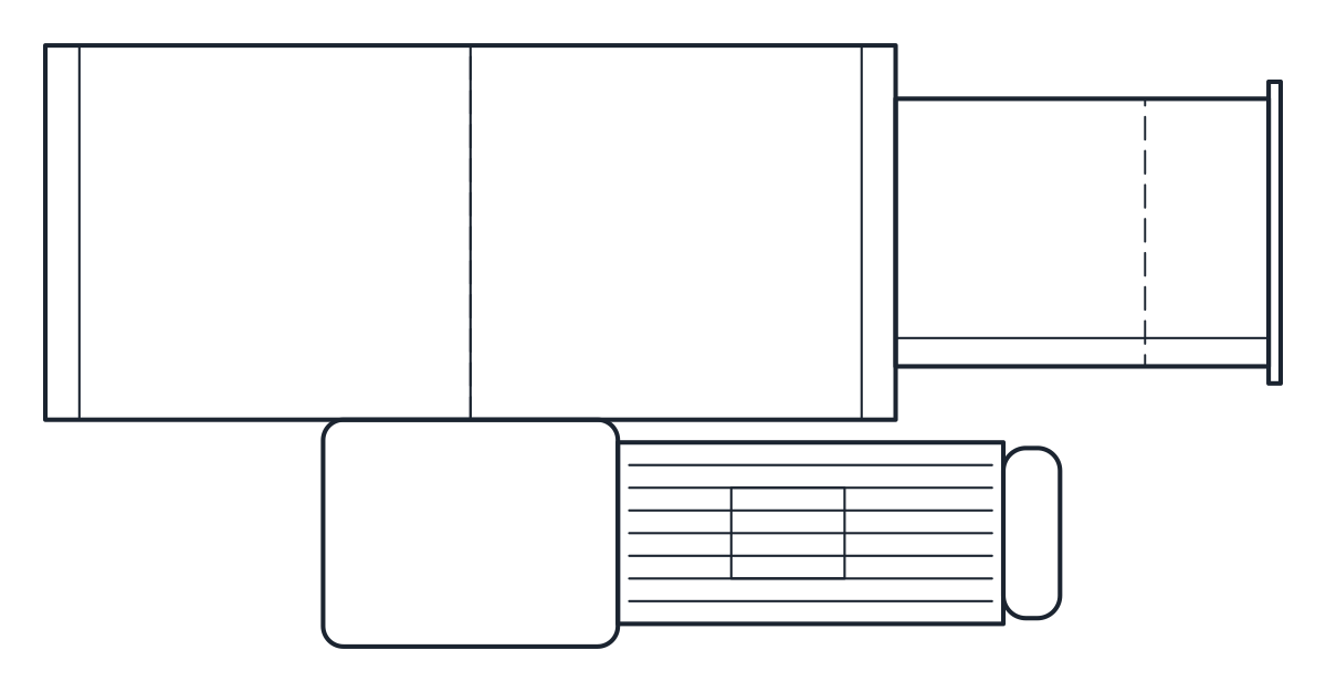
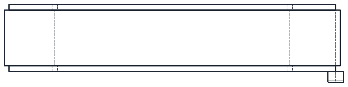
Roller Conveyor CAD Block
Gravity and powered roller conveyors, 600 mm between frames, 3000 mm long, Ø50 rollers at 60 or 120 mm pitch.
Gravity roller conveyor, 600 mm between frames, 3000 mm long
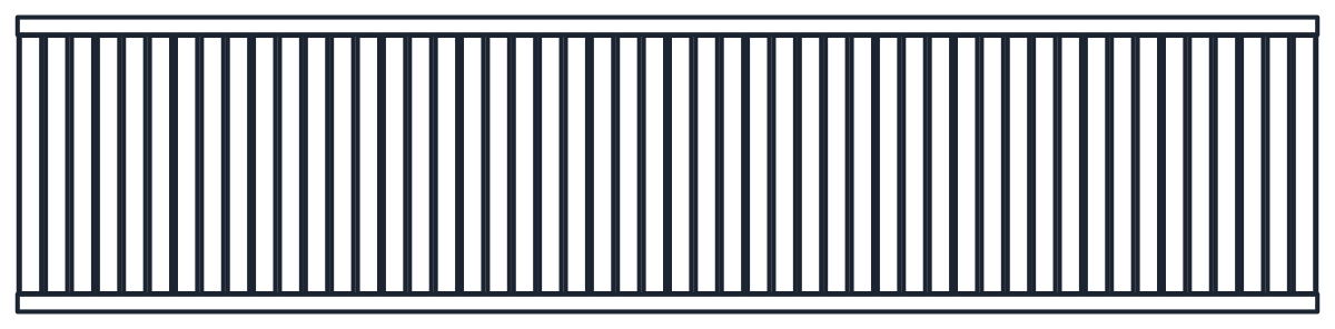
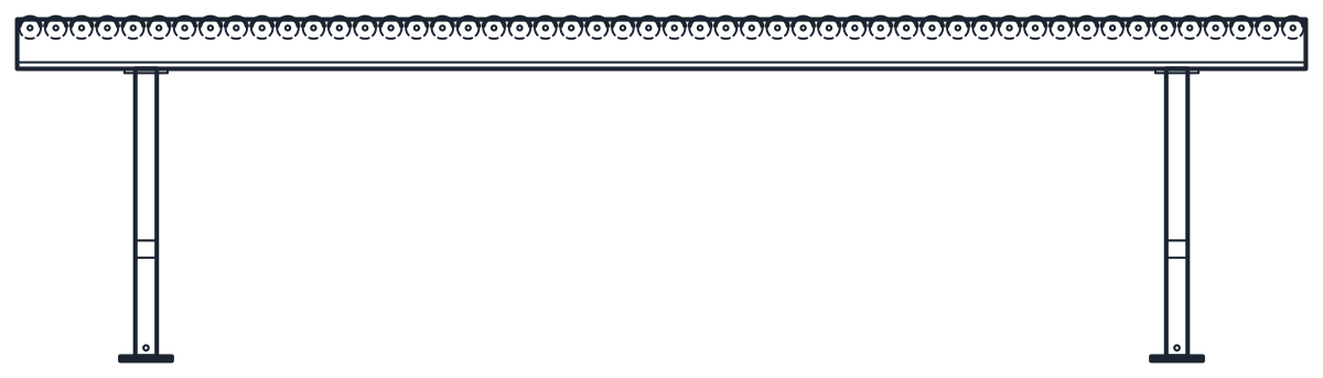
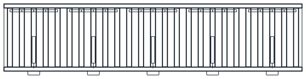
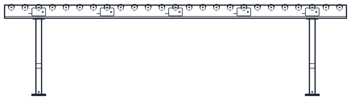
Powered roller conveyor (24 V motor-driven rollers), 600 mm between frames, 3000 mm long
- Units
- Millimetres (INSUNITS 4), drawn at paper size
- Formats
- DWG 2010 · DXF R2010
- Opens in
- AutoCAD and AutoCAD LT 2010 or later, BricsCAD, ZWCAD and DraftSight. The DXF opens in most CAD programs.
- Views
- Plan view + Front elevation
- License
- Free for personal and commercial projects. License
This roller conveyor CAD block download holds two straight roller conveyors, each 600 mm between frames and 3000 mm long, drawn in plan and elevation in millimetres in the DWG and DXF: a gravity conveyor with idler rollers and a powered conveyor with 24 V motor-driven rollers.
Roller conveyor CAD block dimensions
Both variants use 50 mm diameter rollers between 40 mm side frames with a 115 mm profile. The module width is the width between frames plus 80 mm, so 680 mm, as in a typical maker's straight roller conveyor datasheets. The width between frames is drawn at 600 mm, while that maker's standard widths are 420, 620 and 840 mm, with other widths on request. Check which width your supplier builds before you fix the layout.
The gravity conveyor has 50 idler rollers at 60 mm pitch, one of the four pitches the maker lists (60, 90, 120 and 150 mm). The powered conveyor has 25 rollers at 120 mm pitch, grouped in five 600 mm zones. In each zone one motor-driven roller, 24 or 48 V, drives the other four through poly-V belts, and a control card box sits on the front side frame.
Gravity and powered roller conveyor drawing in plan and elevation
The plan shows the rollers, the side frames and, on the powered version, the motor-driven roller of each zone and the control card boxes. Those boxes stand out from the frame, which is why the powered plan is 720 mm wide and the gravity plan 680 mm. The elevation shows the side frame, the rollers on top and two floor supports. The top of roller is at 800 mm, but supports are ordered separately, so the height is representative. Outlines are on layer M-CONV, details on M-CONV-DETL and hidden lines on A-HIDN.
Using the roller conveyor block in a layout
Copy the 3000 mm modules along the product flow and keep the same width between frames so that loads cross from one module to the next. The gravity version needs a slope or a push to move loads, so set the supports with the fall you want in the elevation. On the powered version, place the control card boxes on the side you can reach, since that is where the wiring and the sensors connect.
The motor-driven rollers appear on the schematic with the motor symbol. For flat product or a steady run between stations, see the belt conveyor CAD block.