Belt Conveyor CAD Block
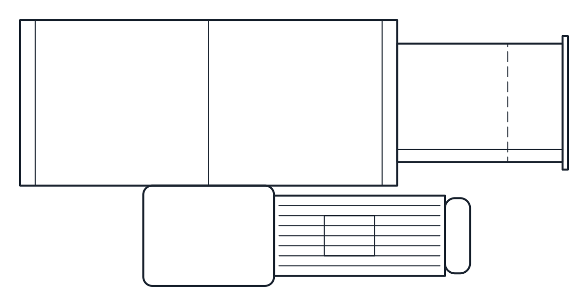
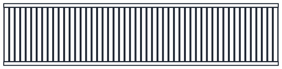
Flat belt conveyors of 500 x 3000 mm and 800 x 6000 mm, belt top at 800 mm, with an end drive.
Flat belt conveyor, 500 mm belt, 3000 mm long, end drive
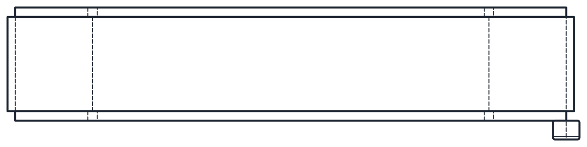
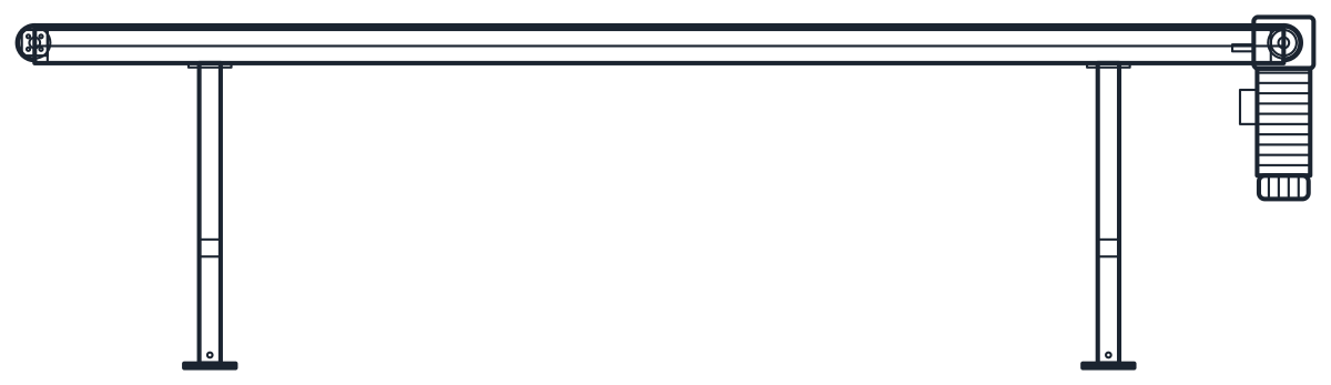
Flat belt conveyor, 800 mm belt, 6000 mm long, end drive


- Units
- Millimetres (INSUNITS 4), drawn at paper size
- Formats
- DWG 2010 · DXF R2010
- Opens in
- AutoCAD and AutoCAD LT 2010 or later, BricsCAD, ZWCAD and DraftSight. The DXF opens in most CAD programs.
- Views
- Plan view + Front elevation
- License
- Free for personal and commercial projects. License
This belt conveyor CAD block download holds two flat belt conveyors with an end drive, drawn in plan and front elevation in millimetres in the DWG and DXF: a 500 mm belt 3000 mm long and an 800 mm belt 6000 mm long.
Belt conveyor CAD block dimensions
Both are slider-bed conveyors: a steel side frame on H-supports, a drive drum and a return drum of 81 mm diameter, and a gearmotor on the drive drum shaft with the motor hanging below the frame. The 500 mm belt sits in a 600 mm wide frame, 700 mm with the gearbox, with an 80 mm frame profile. This is the layout of a typical catalogue conveyor with 81 mm drums and a 0.37 kW gearmotor.
The 800 mm belt uses a 900 mm frame, 1000 mm with the gearbox, after the same rule of frame width = belt width + 100 mm. Another maker quotes a module width of belt width + 80 mm, so the frame width of the large conveyor is indicative. Check the frame width of the conveyor you buy before you set the aisle widths.
Belt conveyor drawing in plan and elevation
The plan is drawn with the conveying length along x and the gearbox on the front side. The block is 3030 mm and 6030 mm long, because the gearbox stands 30 mm out past the drum, while the conveying length is 3000 mm and 6000 mm. The front elevation shows the belt loop round both drums, the side frame, the supports and the gearmotor.
The belt top is at 800 mm above the floor, with H-supports every 2.1 to 2.5 m: two supports on the 3 m conveyor and three with diagonal bracing on the 6 m one. Working height and support spacing depend on the supports you order, so these values are representative. Outlines are on layer M-CONV, details on M-CONV-DETL and hidden lines on A-HIDN.
Using the belt conveyor block in a production line layout
Lay the blocks end to end along the product flow and check the transfer between them in the elevation, where the drum diameter and the belt top meet. Leave space on the gearbox side for maintenance, and keep the motor under the frame clear of floor drains and kick plates. If the line has to run at another working height, move the belt and frame together and keep the drums in place relative to the frame.
The drive motor appears on the schematic with the motor symbol. Where the product needs to accumulate or turn, a roller section is often added, and you will find it in the roller conveyor CAD block.