Screw Conveyor CAD Block
A tubular screw conveyor with a 250 mm screw in a 4000 mm tube of 266 mm OD, axis at 700 mm.
Tubular screw conveyor, 250 mm screw, 4000 mm tube, inlet hopper and inline gearmotor

- Units
- Millimetres (INSUNITS 4), drawn at paper size
- Formats
- DWG 2010 · DXF R2010
- Opens in
- AutoCAD and AutoCAD LT 2010 or later, BricsCAD, ZWCAD and DraftSight. The DXF opens in most CAD programs.
- Views
- Plan view + Front elevation
- License
- Free for personal and commercial projects. License
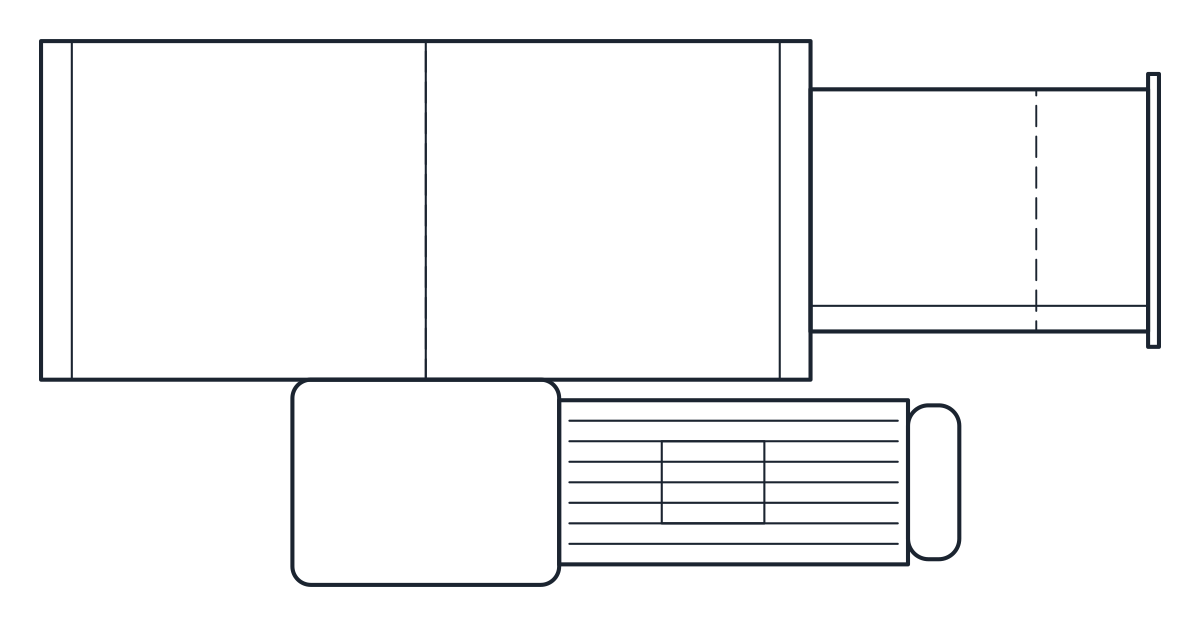
This screw conveyor CAD block download holds one tubular screw conveyor with a 250 mm screw in a 4000 mm tube, an inlet hopper and an inline gearmotor, drawn in plan and elevation in millimetres in the DWG and DXF.
Screw conveyor CAD block dimensions
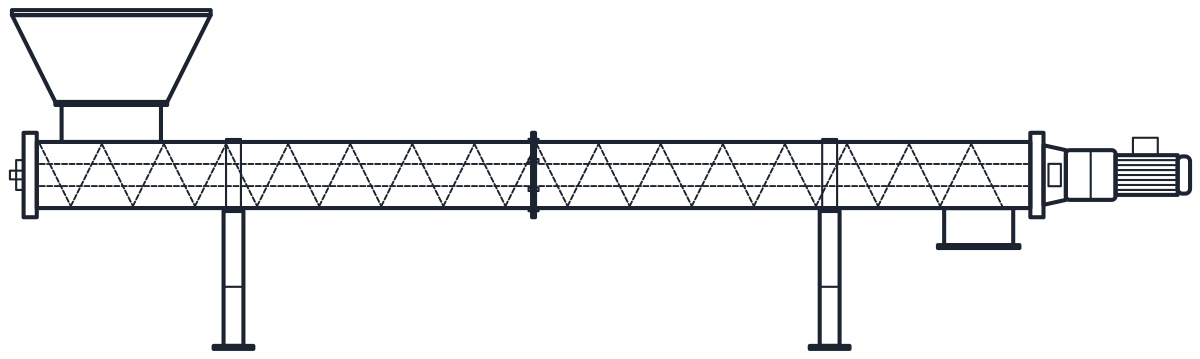
The conveyor follows a manufacturer's datasheet for its 250 size. The 250 mm screw runs in a tube of 266 mm outside diameter, built from two 2000 mm sections joined by 340 mm flanges. The inlet is 400 mm long with a 450 mm flange. At both ends the shaft runs in 35 mm journals with 53 mm end plates. The pyramid hopper above the inlet, 800 x 800 mm at the top, is representative.
The datasheet leaves the drive to the application, so the gearmotor size in the drawing is representative too. Check the drive and the hopper with your supplier, since both change with the material and the capacity.
Tubular screw conveyor drawing in plan and elevation
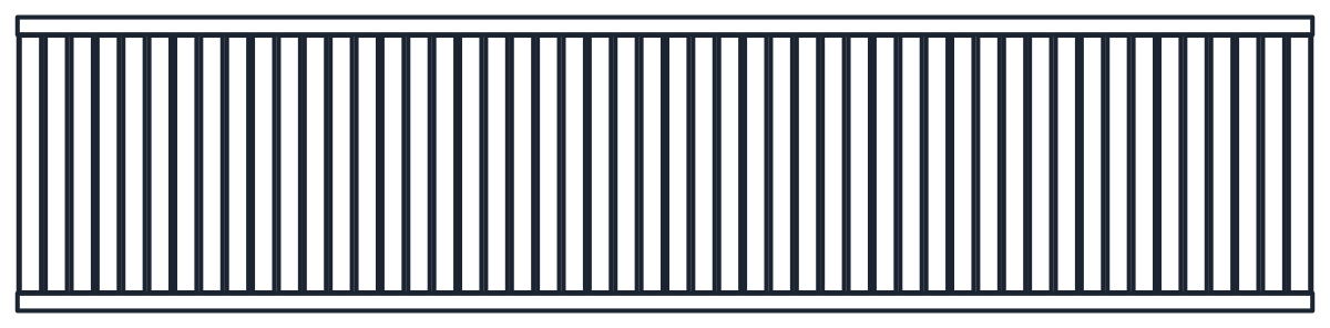
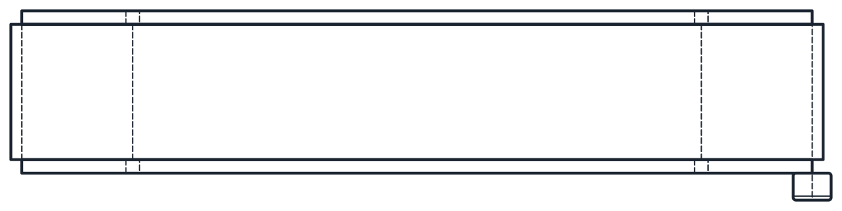
The plan shows the tube, the flanges, the inlet with its hopper and the drive from above. The elevation shows the same parts from the side. The screw flight, with a pitch equal to the 250 mm diameter, and the 88.9 mm centre pipe are drawn as hidden lines on layer A-HIDN. Outlines are on M-CONV and details on M-CONV-DETL.
The drive sits at the discharge end: a lantern, the gear unit and the motor in line with the screw. That is why the block is 4751 mm long, more than the 4000 mm tube. The tube axis is at 700 mm on two clamp supports. On site this kind of conveyor is usually hung from the structure or supported to suit the plant, so the support height is representative.
Using the screw conveyor block under a silo or hopper
Place the inlet under the outlet of the silo or bin it feeds, and check in the elevation that the hopper fits under the discharge. If the conveyor has to sit higher or lower, move the supports and keep the tube, the flanges and the drive together. Leave space behind the motor at the discharge end for removing the drive, and keep the tube flanges reachable for inspection.
The drive motor appears on the schematic with the motor symbol. To lift the same material vertically, see the bucket elevator CAD block.