Gearmotor CAD Block
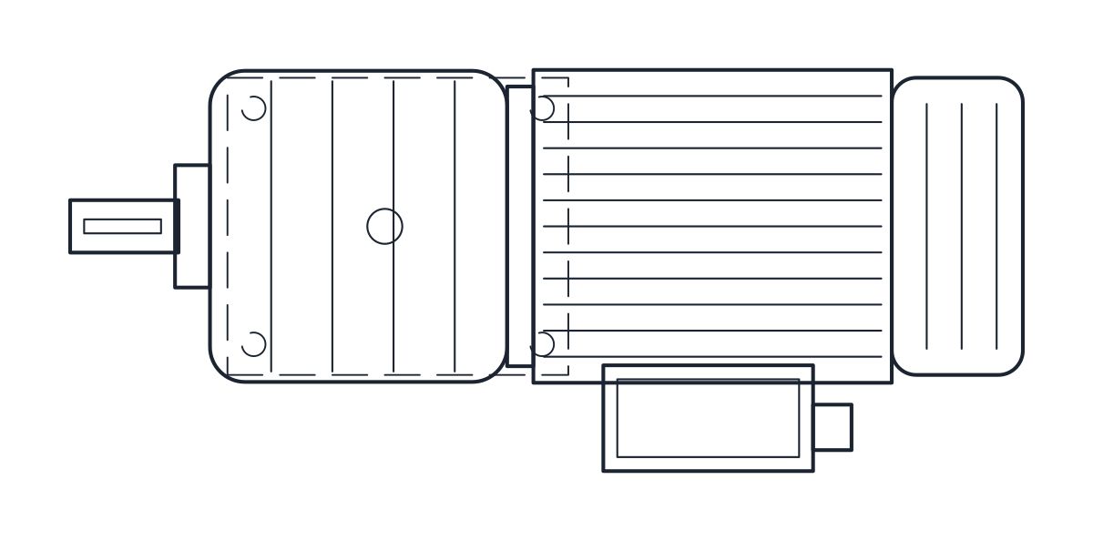
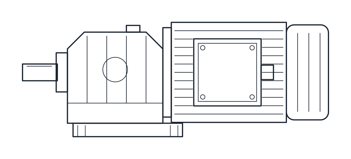
A helical inline gearmotor, 545 mm long, with a Ø30 x 60 mm output shaft at 115 mm and 195 x 170 mm feet.
Helical inline gearmotor, size R47 with 90L motor, foot mounted
- Units
- Millimetres (INSUNITS 4), drawn at paper size
- Formats
- DWG 2010 · DXF R2010
- Opens in
- AutoCAD and AutoCAD LT 2010 or later, BricsCAD, ZWCAD and DraftSight. The DXF opens in most CAD programs.
- Views
- Plan view + Front elevation
- License
- Free for personal and commercial projects. License
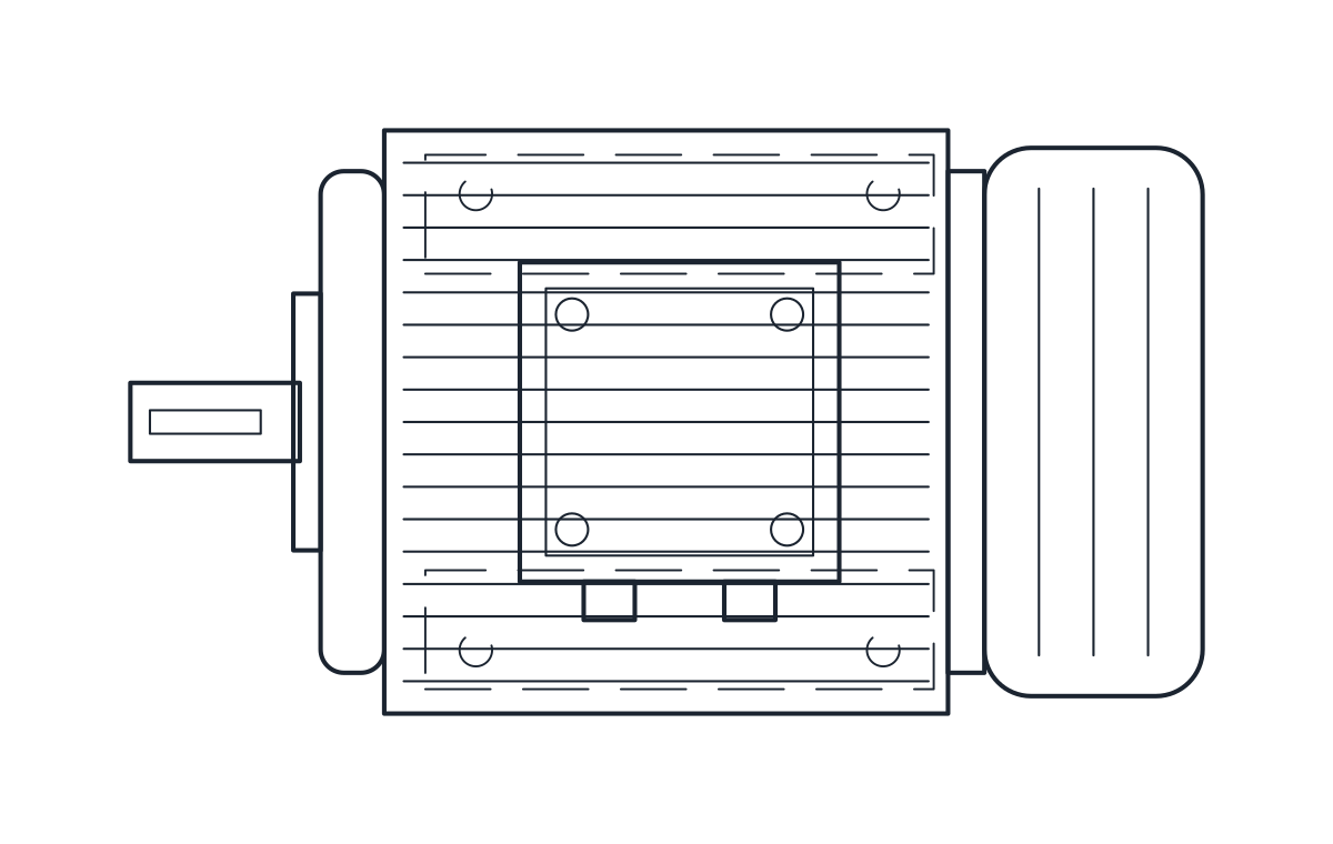
This gearmotor CAD block download holds one foot-mounted helical inline gearmotor, a gear unit with a frame 90L motor, drawn in plan and elevation in millimetres in the DWG and DXF. It is 545 mm long with a Ø30 x 60 mm output shaft at a height of 115 mm.
Gearmotor CAD block dimensions
The dimensions come from the official dimension sheet of a common helical inline gear unit with a 90L motor. The overall length is 545 mm, the output shaft is Ø30 x 60 mm and the shaft height is 115 mm. The gear housing is 178 mm wide and 187 mm high. The feet measure 195 x 170 mm, with Ø13.5 mm holes at 165 x 135 mm centres. The motor has a fin diameter AC of 179 mm and the terminal box reaches AD 140 mm from the axis, both from the same sheet.
These are the values of one catalogue product. Gearmotors of a similar size from other makers use their own housings and feet, so check the dimension sheet for the unit and motor you order.
Helical gearmotor drawing in plan and elevation
The plan shows the gear housing, the motor and the output shaft from above, with the feet and their holes. The elevation shows the shaft at 115 mm, the housing, the motor flange, the motor body and the fan cover. The terminal box is drawn facing the front. The outline of the housing, the size of the terminal box and the fan cover are drawn by us and are representative.
Outlines are on layer E-EQPM, details on E-EQPM-DETL and hidden lines on A-HIDN.
Using the gearmotor block on a conveyor or mixer drive
Place the block by the output shaft, lined up with the shaft of the driven machine, and mark the four foot holes from the 165 x 135 mm centres. The output shaft height of 115 mm is not the IEC frame height of the motor, because the gear unit sets its own shaft height. If the terminal box has to face the other way on site, mirror the block across the shaft axis and check that the cable still reaches it.
On the schematic the drive is shown as a motor, a circle with an M, and the block is on the motor symbol page. For a plain foot-mounted motor by IEC frame size, see the electric motor CAD block.