Transformer CAD Block
A 630 kVA, 12 kV cast resin transformer in open execution, 1390 x 820 x 1860 mm.
Cast resin dry-type transformer 630 kVA 12 kV, open IP00, 1390 x 820 x 1860
- Units
- Millimetres (INSUNITS 4), drawn at paper size
- Formats
- DWG 2010 · DXF R2010
- Opens in
- AutoCAD and AutoCAD LT 2010 or later, BricsCAD, ZWCAD and DraftSight. The DXF opens in most CAD programs.
- Views
- Plan view + Front elevation
- License
- Free for personal and commercial projects. License
This transformer CAD block download holds one cast resin dry-type transformer, 630 kVA, 12 kV class, in open execution (IP00), drawn in plan and elevation in millimetres in the DWG and DXF. The overall size is 1390 x 820 x 1860 mm.
Transformer CAD block dimensions
The overall size comes from the technical data table of a typical catalogue cast resin transformer, 630 kVA, 12 kV class, with an impedance voltage uk of 6 %. The length is 1390 mm, the width 820 mm and the height 1860 mm, and the table gives a weight of about 2030 kg, which is useful when you check the floor and the route into the room. The table only gives the overall dimensions, so check the drawing of the transformer you order, especially if it has a different power, voltage or loss class.
Dry type transformer drawing in plan and elevation
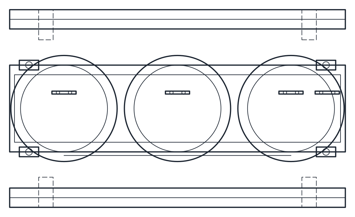
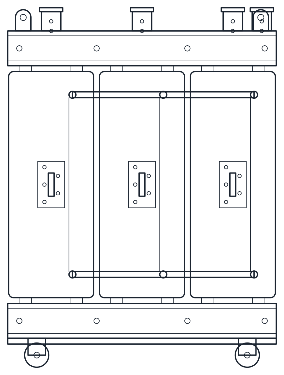
The transformer is drawn in open execution on lockable castors. The three encapsulated coils stand side by side, with the delta connection bars on the front and the LV busbars on top. The coil spacing of 470 mm, the coil diameter and the 125 mm castors are representative, because the maker's table does not give them. The yoke heights and the shape of the LV bars are also drawn by us.
The plan shows the three coils and the frame from above in 1390 x 820 mm. The elevation shows the coils, the yokes and clamping profiles, the connection bars and the busbars. Outlines are on layer E-EQPM, details on E-EQPM-DETL and hidden lines on A-HIDN.
Using the transformer block in a substation room
An open IP00 transformer has no protection against contact, so it goes inside a locked electrical room or behind a guard. If you plan an enclosure around it, the outside dimensions change and are not covered by this block. Use the plan to set the clearances to the walls and to the switchgear, and the elevation to check the height of the LV busbars against the cable tray or the busbar trunking that connects to them.
On the single-line diagram the transformer is drawn as two overlapping circles, and the block is on the motor symbol page together with the motor and the generator. For the low voltage panels it feeds, see the electrical cabinet CAD block.