Electric Motor CAD Block
Foot-mounted IEC motors with shaft heights of 90, 132, 180 and 250 mm, 329 to 965 mm long.
IEC frame 90L electric motor, foot mounted B3, shaft height 90
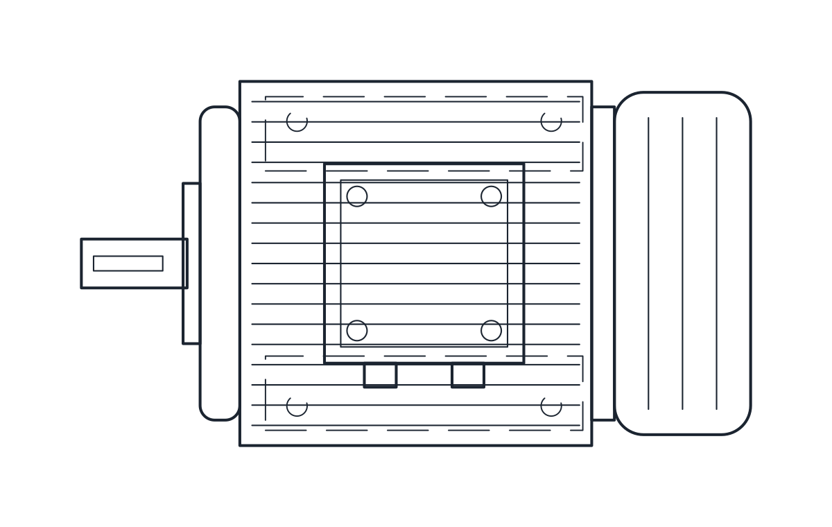
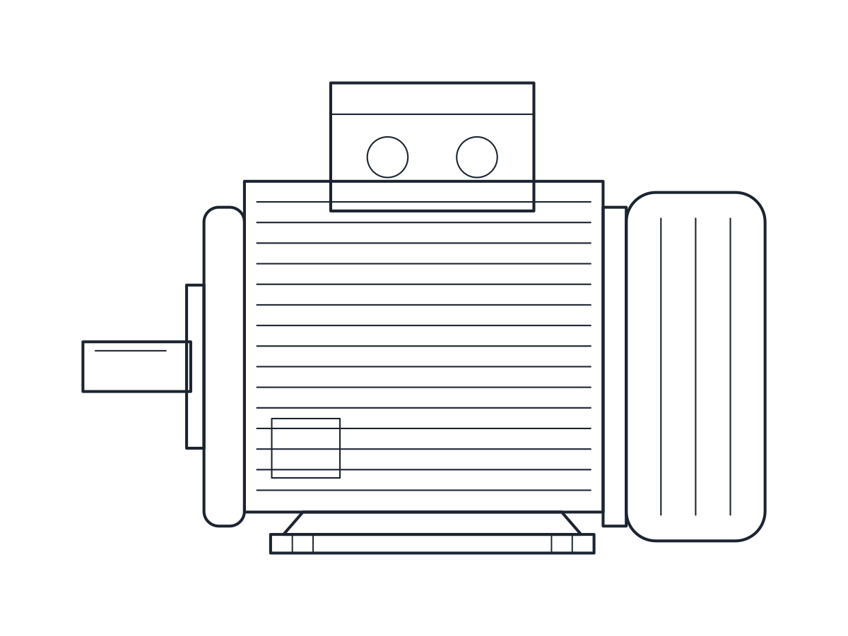
IEC frame 132M electric motor, foot mounted B3, shaft height 132
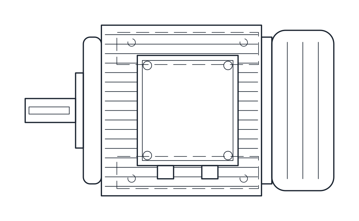
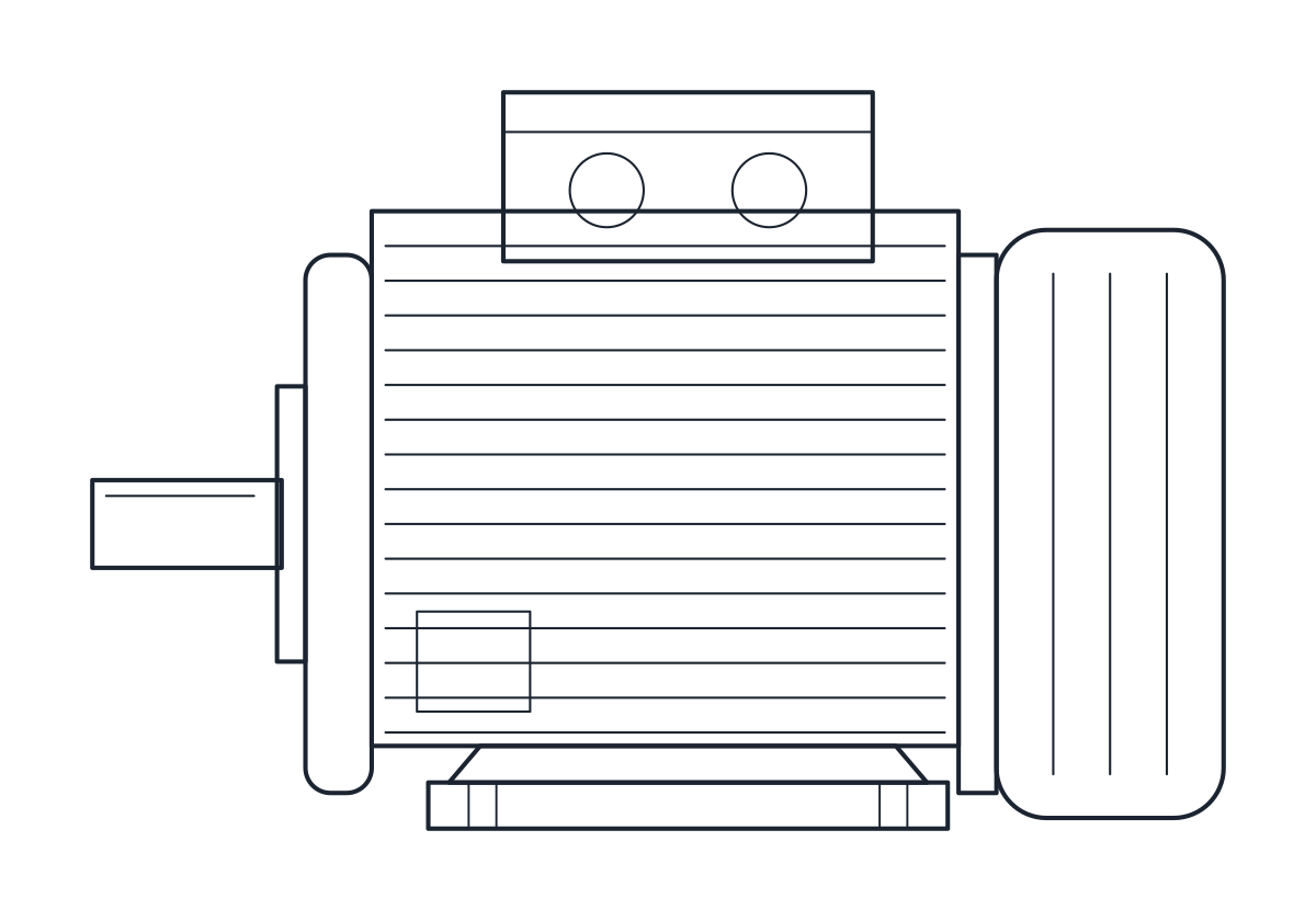
IEC frame 180M electric motor, foot mounted B3, shaft height 180
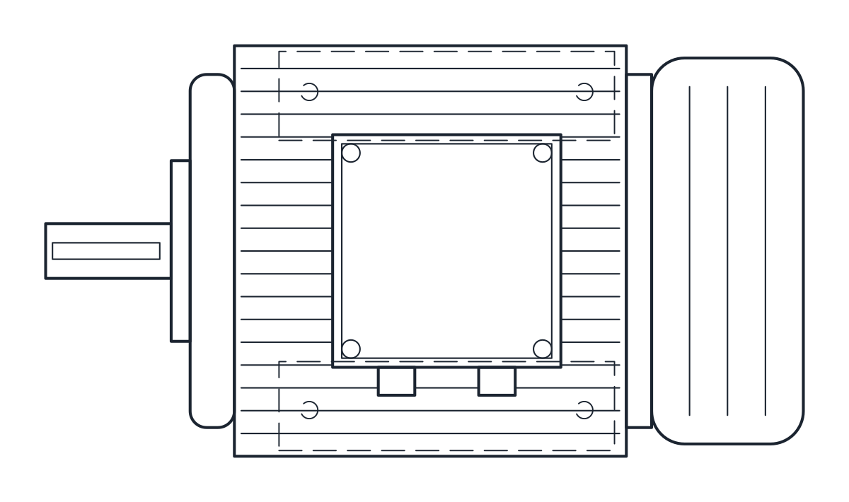
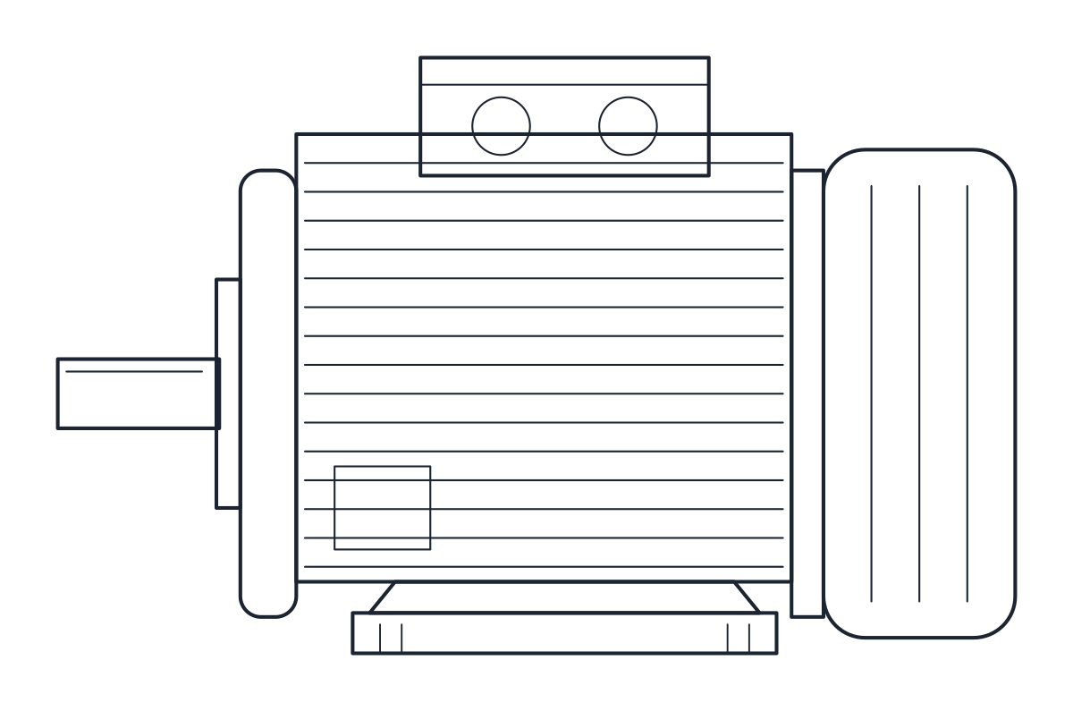
IEC frame 250M electric motor, foot mounted B3, shaft height 250
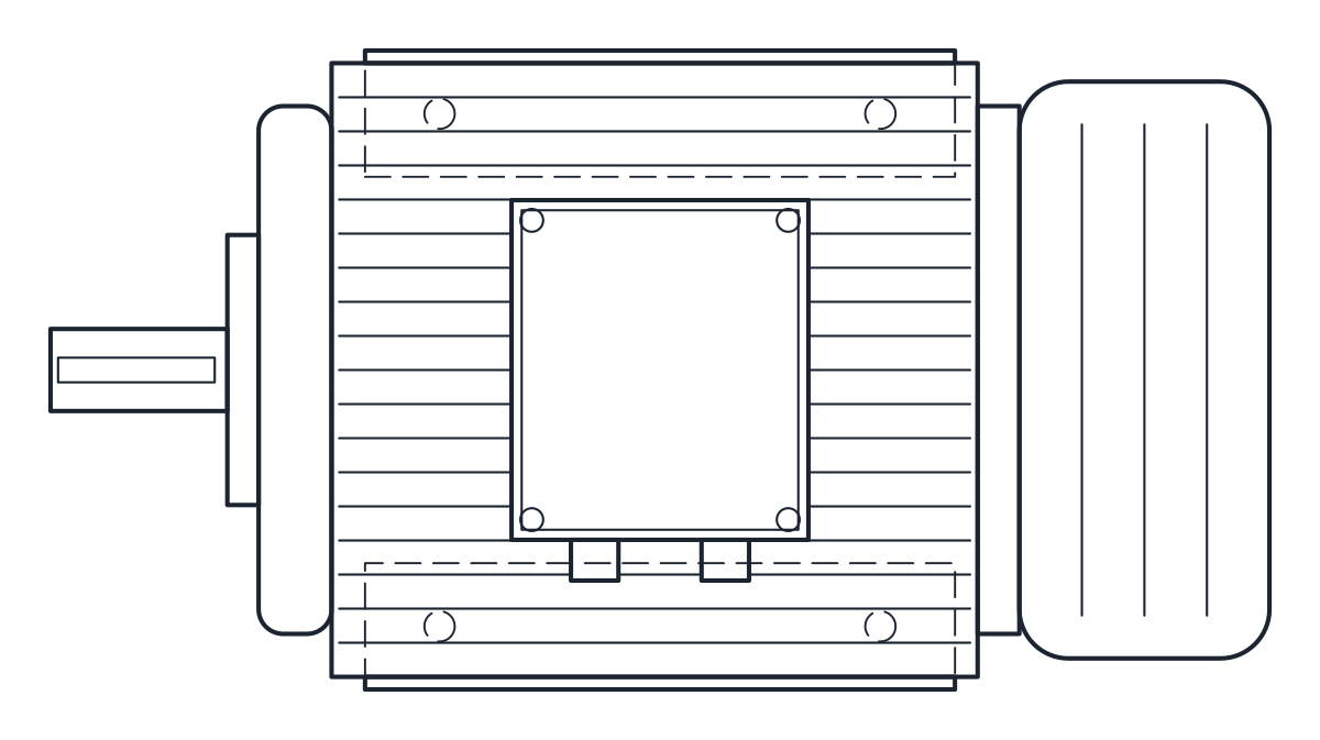
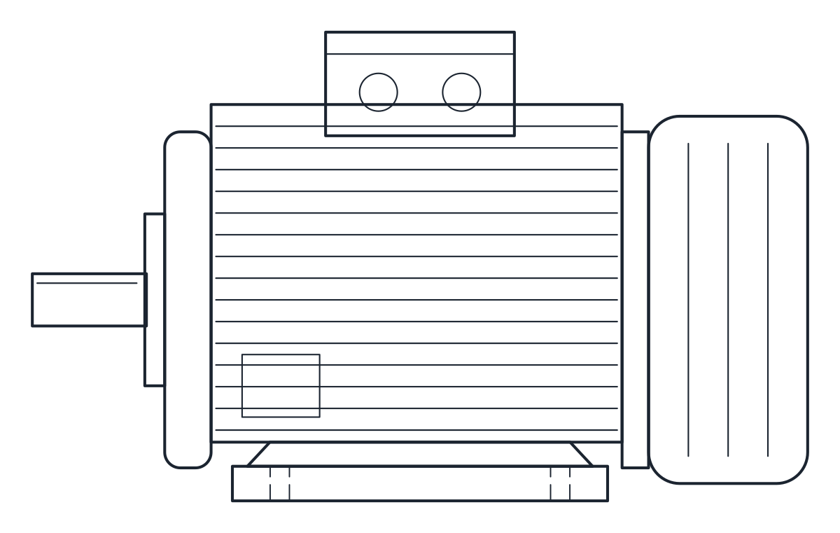
- Units
- Millimetres (INSUNITS 4), drawn at paper size
- Formats
- DWG 2010 · DXF R2010
- Opens in
- AutoCAD and AutoCAD LT 2010 or later, BricsCAD, ZWCAD and DraftSight. The DXF opens in most CAD programs.
- Views
- Plan view + Front elevation
- License
- Free for personal and commercial projects. License
This electric motor CAD block download holds four foot-mounted (IM B3) IEC motors in frame sizes 90L, 132M, 180M and 250M, so with shaft heights of 90, 132, 180 and 250 mm, each drawn in plan and elevation in millimetres in the DWG and DXF.
Electric motor CAD block by IEC frame size
In an IEC motor the frame number is the shaft height. IEC 60072-1 sets it in millimetres, from the face of the feet to the shaft axis, whoever makes the motor. The same standard fixes the mounting dimensions for each frame: A is the distance between the foot holes across the motor, B the distance between them along the motor, C the distance from the shaft shoulder to the nearest foot holes, and K the hole diameter. The blocks use the values of the IEC mounting table as printed in a major maker's catalogue:
- 90L: A 140, B 125, C 56, K 10, shaft 24 x 50 mm
- 132M: A 216, B 178, C 89, K 12, shaft 38 x 80 mm
- 180M: A 279, B 241, C 121, K 15, shaft 48 x 110 mm
- 250M: A 406, B 349, C 168, K 24, shaft 65 x 140 mm (4 pole)
Electric motor drawing in plan and elevation
The rest of the body is a typical catalogue motor. Overall length L and fin diameter AC are 329 and 179 mm for the 90L, 490 and 271 mm for the 132M, 664 and 360 mm for the 180M, and 965 and 486 mm for the 250M. The height to the top of the terminal box is 319, 413 and 583 mm for frames 132, 180 and 250. For frame 90 the 227 mm is an estimate, because that column of the table could not be read reliably. Terminal box size, fin pitch and fan cover proportions are representative and change between makers, so check L, AC and the terminal box against the sheet of the motor you buy.
Outlines are on layer E-EQPM, fins and details on E-EQPM-DETL and hidden lines on A-HIDN.
Using the motor block on a baseplate or pump skid
Line up the shaft axis with the driven machine, then mark the four foot holes from A, B and K. Because these dimensions are standard, the holes stay valid for another make of the same frame. Leave room behind the fan cover for cooling air.
On the schematic the motor is a circle with an M, which you will find on the motor symbol page. For a motor with a reduction gear, see the gearmotor CAD block.