Diaphragm Pump CAD Block
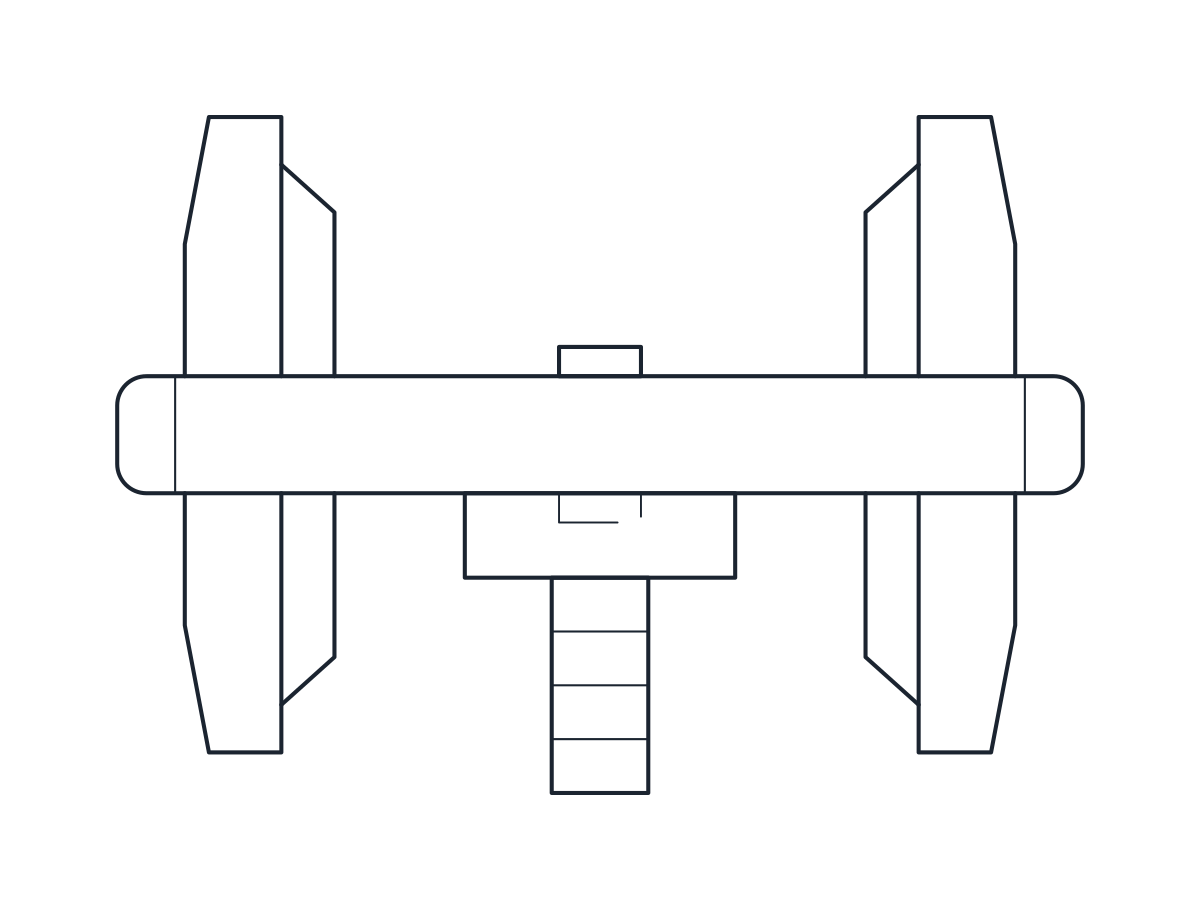
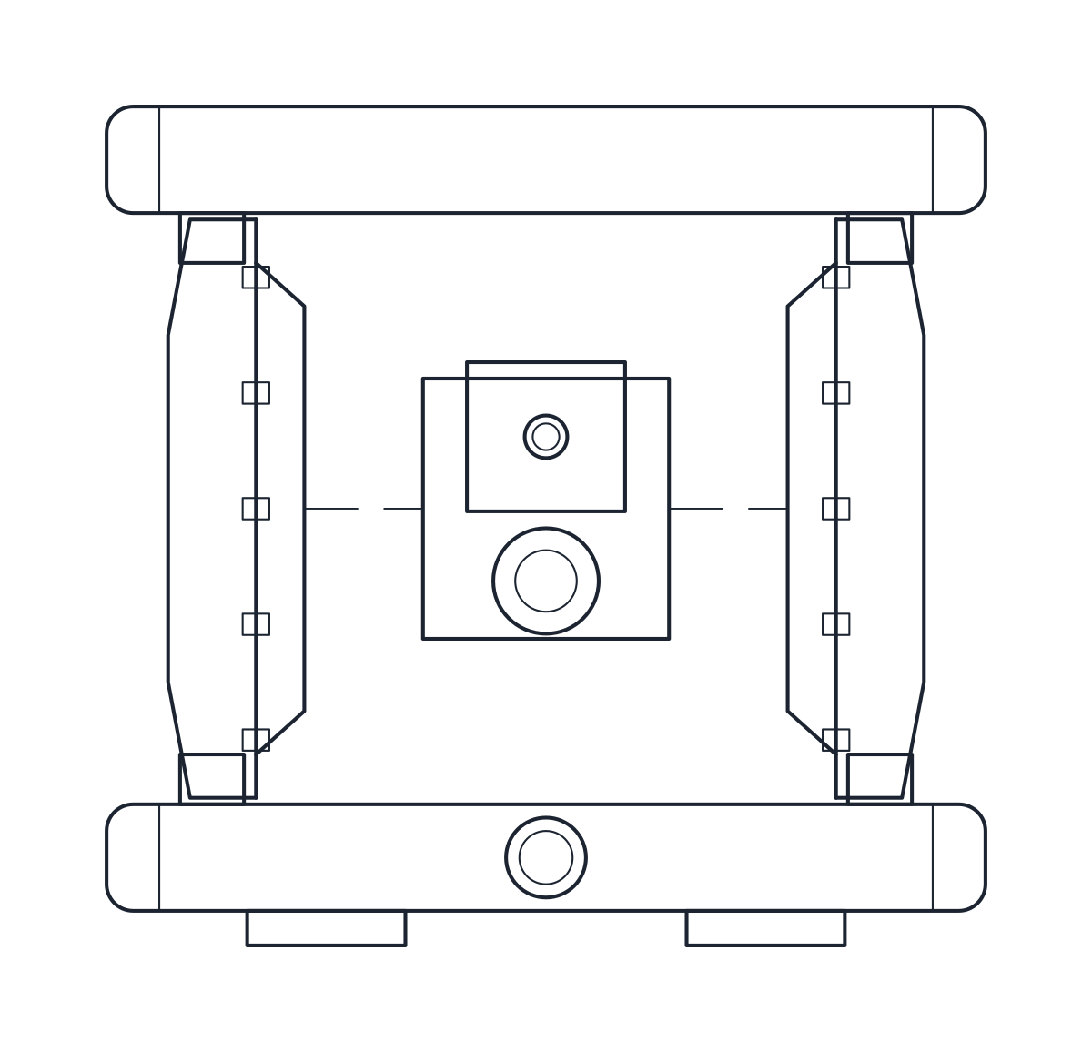
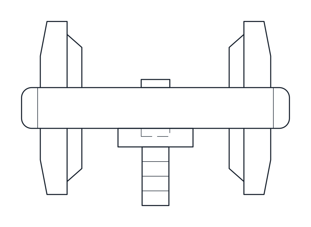
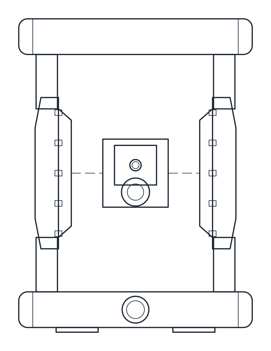
Air-operated double diaphragm pumps of 1 and 2 inch, 330 x 231 x 315 and 498 x 343 x 668 mm.
Air-operated double diaphragm pump 1", aluminium
Air-operated double diaphragm pump 2", aluminium
- Units
- Millimetres (INSUNITS 4), drawn at paper size
- Formats
- DWG 2010 · DXF R2010
- Opens in
- AutoCAD and AutoCAD LT 2010 or later, BricsCAD, ZWCAD and DraftSight. The DXF opens in most CAD programs.
- Views
- Plan view + Front elevation
- License
- Free for personal and commercial projects. License
This download holds two air-operated double diaphragm pumps, or AODD pumps, with aluminium bodies: a 1 inch pump and a 2 inch pump, both with NPT ports. Each has a bottom suction manifold, a top discharge manifold, two fluid chambers, the centre air section and a muffler. Each size comes as a plan block and an elevation block in millimetres at full size, in a DWG for AutoCAD 2010 and later and in a DXF.
Diaphragm pump DWG dimensions
The measurements come from the dimension drawings of a typical catalogue range, so check them against the manual of the pump you buy.
- 1 inch: 330 mm wide, 315 mm high, 231 mm deep; suction axis 33 mm, discharge axis 295 mm and air inlet 191 mm above the floor.
- 2 inch: 498 mm wide, 668 mm high, 343 mm deep; suction axis 48 mm, discharge axis 630 mm and air inlet 356 mm above the floor.
The depth is that of the side view and includes the muffler. The diameter of the fluid chambers, the centre block and the manifold elbows are representative.
Diaphragm pump drawing in plan and elevation
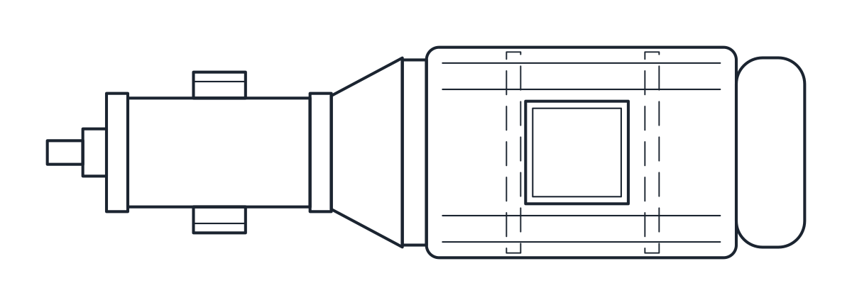
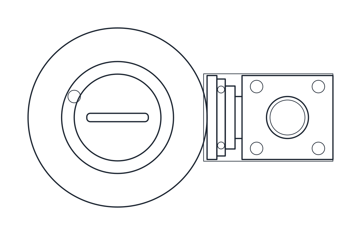
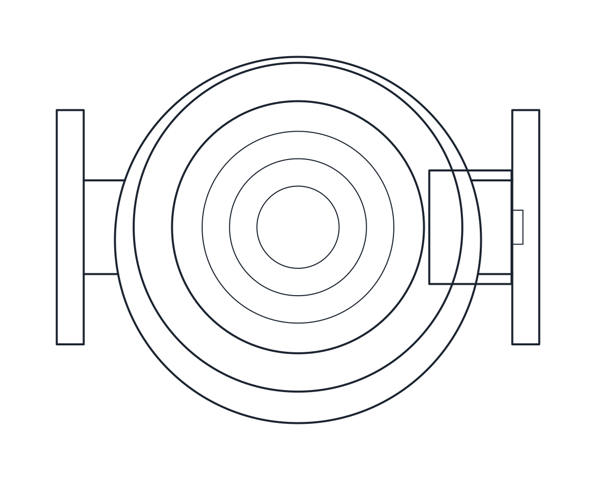
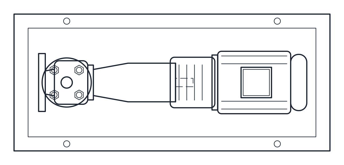
The front elevation shows the two chambers on each side of the air section, joined by the suction manifold at the bottom and the discharge manifold at the top, with the feet under the suction manifold. The plan shows the manifold, the chambers in profile and the muffler sticking out to the front. Hidden lines are on layer A-HIDN.
Using the AODD pump block in a transfer or dosing area
AODD pumps are often placed on the floor next to a drum or tank, or on a small frame. Keep the suction short, route the discharge up from the top manifold and bring the air line to the inlet at 191 or 356 mm. Leave room around the muffler, which exhausts air. For another positive displacement pump driven by an electric motor, see the gear pump block. On a P&ID, use the form your project legend gives for diaphragm pumps or the positive displacement pump symbol.