Inline Pump CAD Block
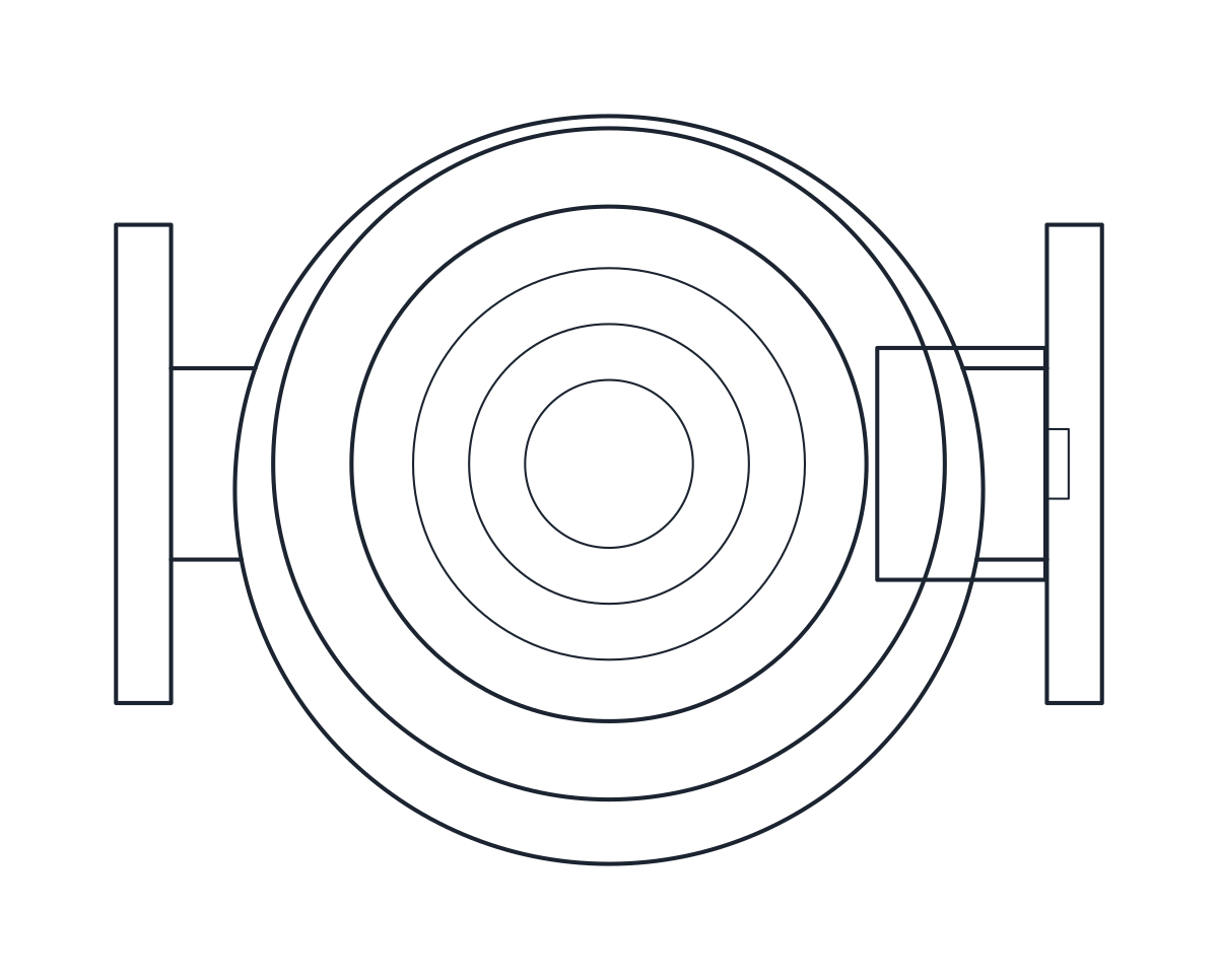
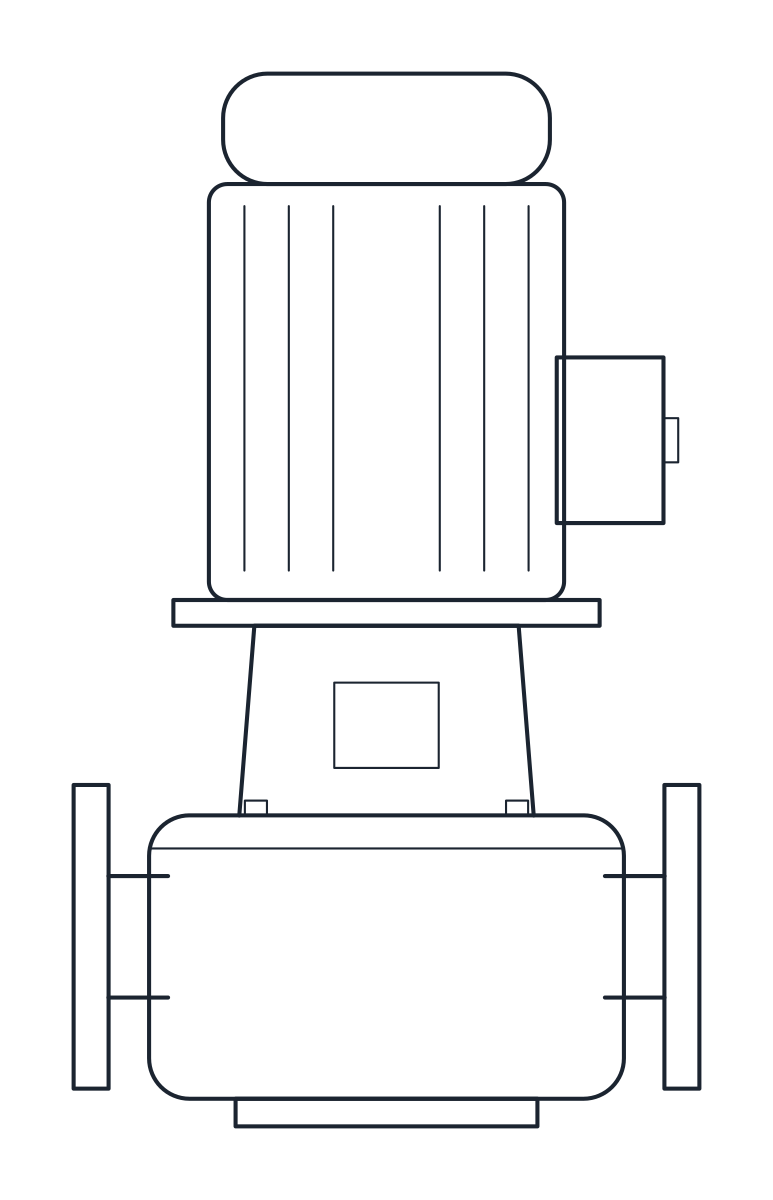
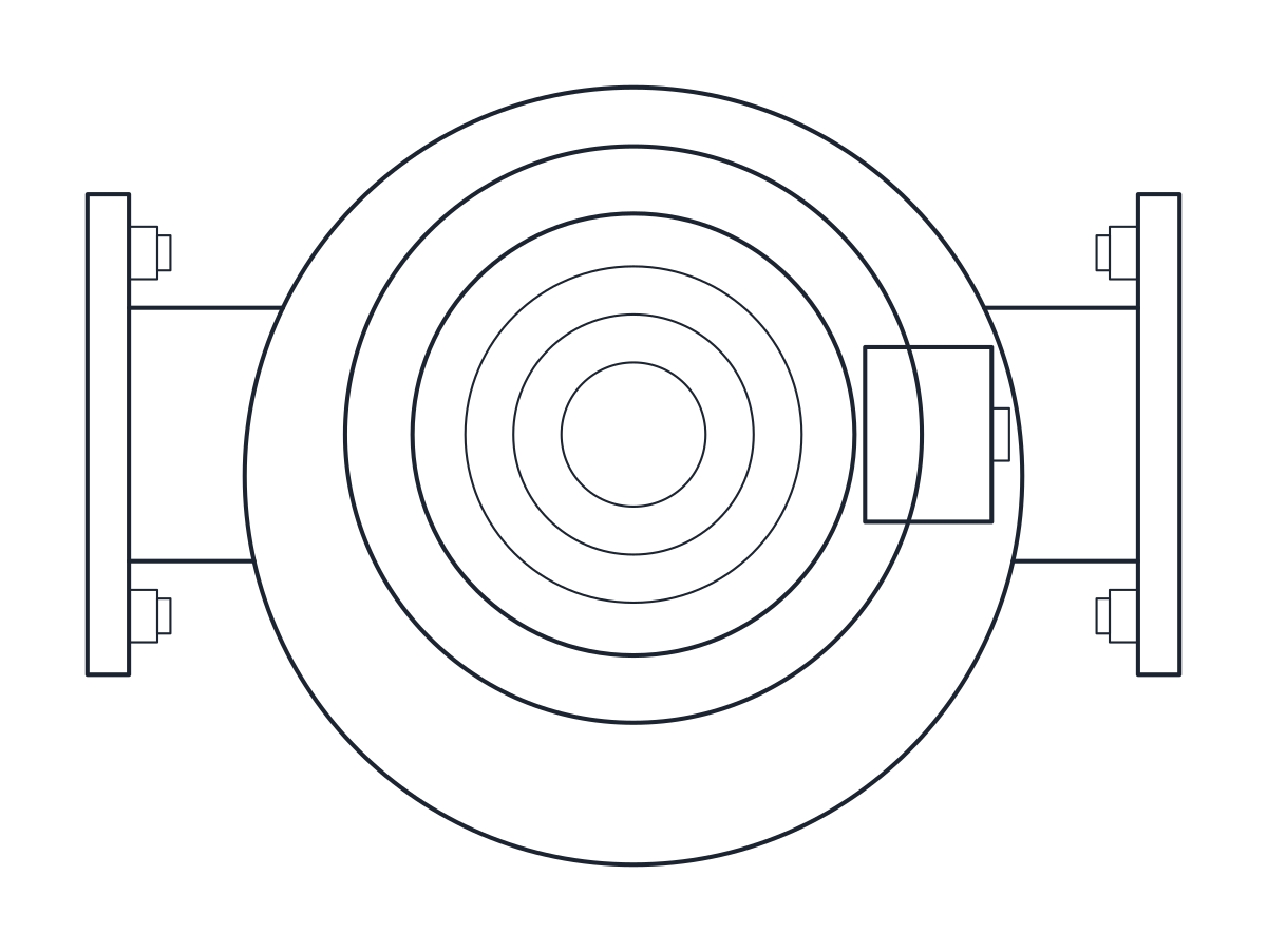
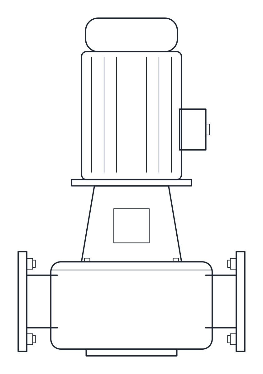
Inline centrifugal pumps DN50 and DN100, 340 and 500 mm port to port and 572 and 745 mm high.
Inline pump DN50 PN16, vertical motor
Inline pump DN100 PN16, vertical motor
- Units
- Millimetres (INSUNITS 4), drawn at paper size
- Formats
- DWG 2010 · DXF R2010
- Opens in
- AutoCAD and AutoCAD LT 2010 or later, BricsCAD, ZWCAD and DraftSight. The DXF opens in most CAD programs.
- Views
- Plan view + Front elevation
- License
- Free for personal and commercial projects. License
This download holds two inline centrifugal pumps with PN16 flanges on a common axis and a vertical standard motor: a DN50 pump with a 1.1 kW 4-pole motor and a DN100 pump with a 3 kW 4-pole motor. Each comes as a plan block and an elevation block in millimetres at full size, in a DWG for AutoCAD 2010 and later and in a DXF.
Inline pump DWG dimensions
The measurements come from the dimension table of a typical catalogue range. Check them against the datasheet of the pump you select, since motors change with the duty point.
- DN50: 340 mm port to port, pipe axis 103 mm above the floor, 469 mm from the axis to the top of the motor, motor 193 mm in diameter, 258 mm deep in plan.
- DN100: 500 mm port to port, pipe axis 120 mm above the floor, 625 mm from the axis to the top of the motor, motor 220 mm in diameter, 356 mm deep in plan.
The overall blocks are 340 x 258 x 572 mm and 500 x 356 x 745 mm. The motor length, the lantern between pump and motor, the terminal box, the feet and the shape of the volute are representative.
Inline pump drawing in plan and elevation
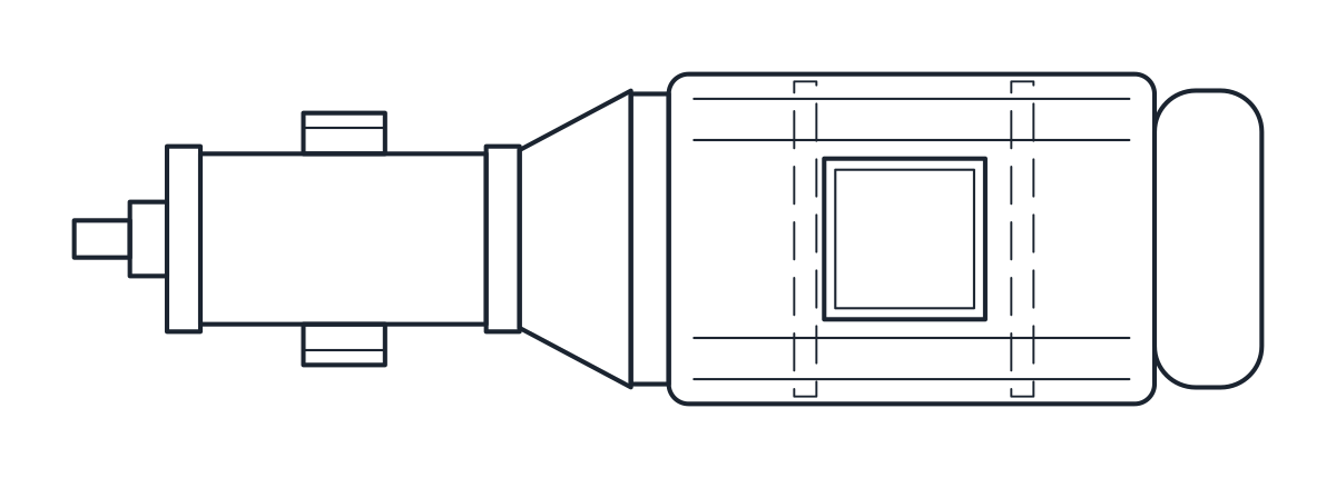
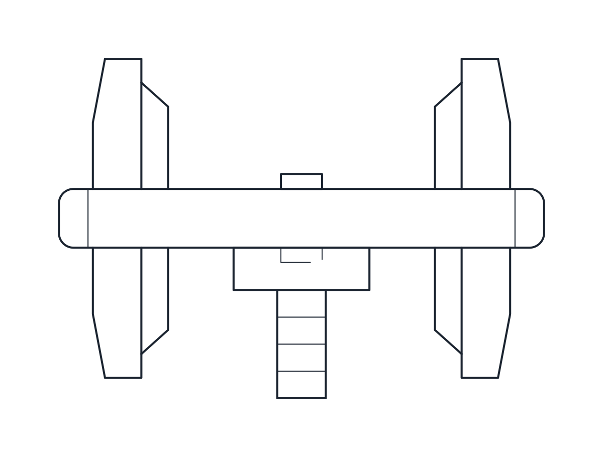
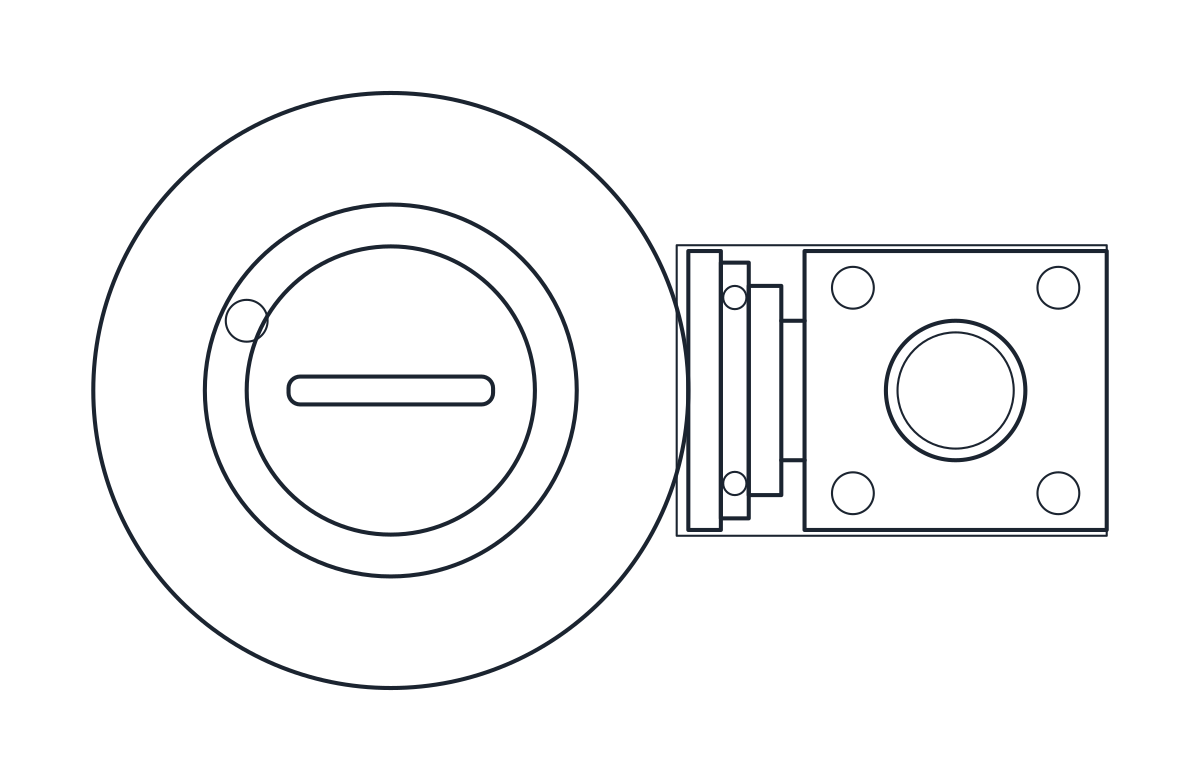
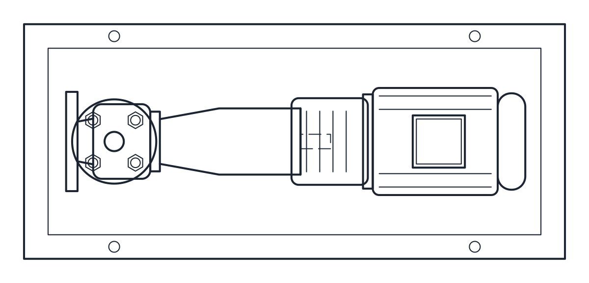
The elevation shows the pump casing with its two flanges, the lantern and the vertical motor with its fan cowl on top. The plan shows the round volute, drawn slightly off the pipe axis, with the two flanges on each side and the terminal box. The pump outlines are on layer M-PUMP and the detail on M-PUMP-DETL.
Using the inline pump block in a heating or cooling circuit
An inline pump goes straight into the pipe run, so the port-to-port length replaces a length of pipe. Insert the plan block with both flange faces on the line. The casing can rest on the floor or hang from the pipe, depending on the size and on your supports. Leave headroom above the motor to lift it out. For a pump on its own baseplate, compare with the end suction pump block. On a P&ID the inline pump uses the same centrifugal pump symbol.