Gear Pump CAD Block
External gear pump with G 1 ports and IEC 90 motor, 640 mm long, 238 mm high and 178 mm wide.
Gear pump G 1 with IEC 90 motor, bell housing
- Units
- Millimetres (INSUNITS 4), drawn at paper size
- Formats
- DWG 2010 · DXF R2010
- Opens in
- AutoCAD and AutoCAD LT 2010 or later, BricsCAD, ZWCAD and DraftSight. The DXF opens in most CAD programs.
- Views
- Plan view + Front elevation
- License
- Free for personal and commercial projects. License
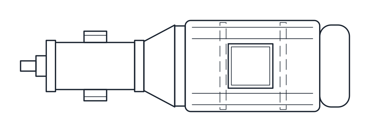
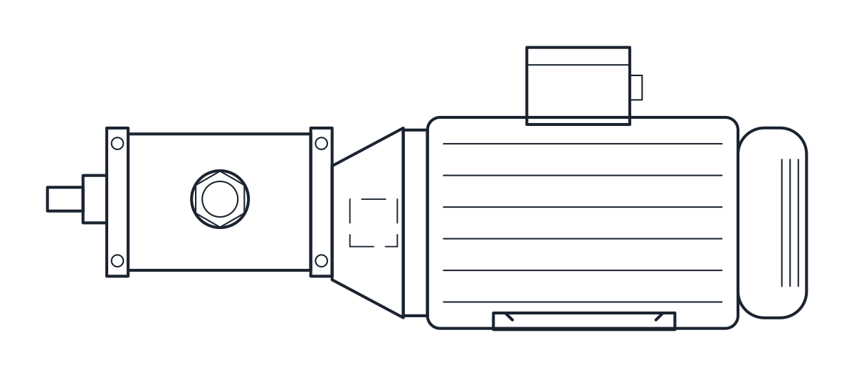
This download holds one set: a cast iron external gear pump with G 1 ports and a built-in relief valve, coupled to an IEC frame 90 foot motor (B34) through a bell housing. It comes as a plan block and an elevation block in millimetres at full size, in a DWG for AutoCAD 2010 and later and in a DXF.
Gear pump DWG dimensions
The measurements come from the dimension table of a typical catalogue pump and motor set. Check them against the drawing of the set you order.
- Overall length 640 mm: 590 mm from the front of the pump to the end of the motor plus 50 mm for the relief valve.
- Overall height 238 mm, with the G 1 ports 110 mm above the feet.
- Pump body 136 mm wide, motor foot holes 125 x 140 mm.
The motor shaft sits 90 mm above the feet, because the IEC frame number is the shaft height (IEC 60072-1). The motor is drawn 178 mm in diameter, a representative value for frame 90, and the bell housing, the pump body and the terminal box are also representative. The source table marks overall height and motor length as depending on the motor maker, so confirm them once the motor is chosen.
Gear pump drawing in plan and elevation
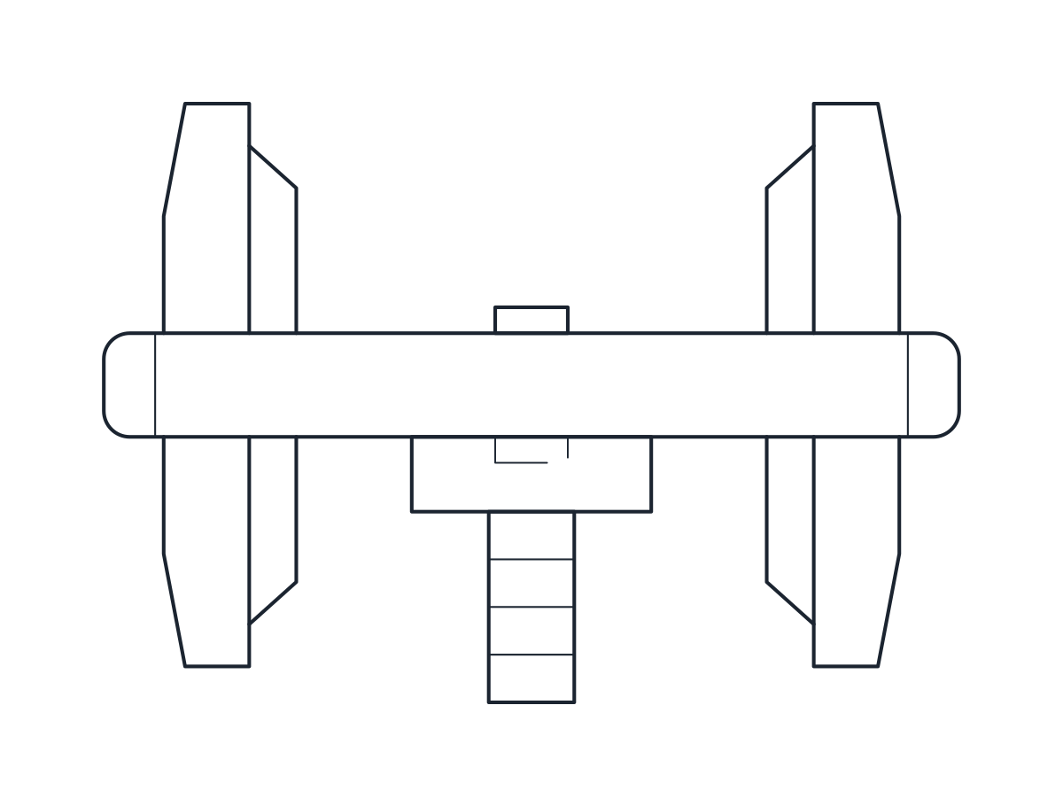
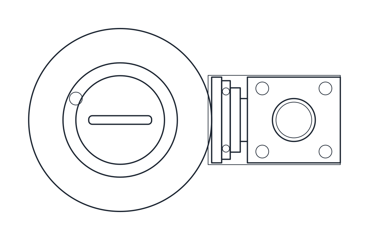
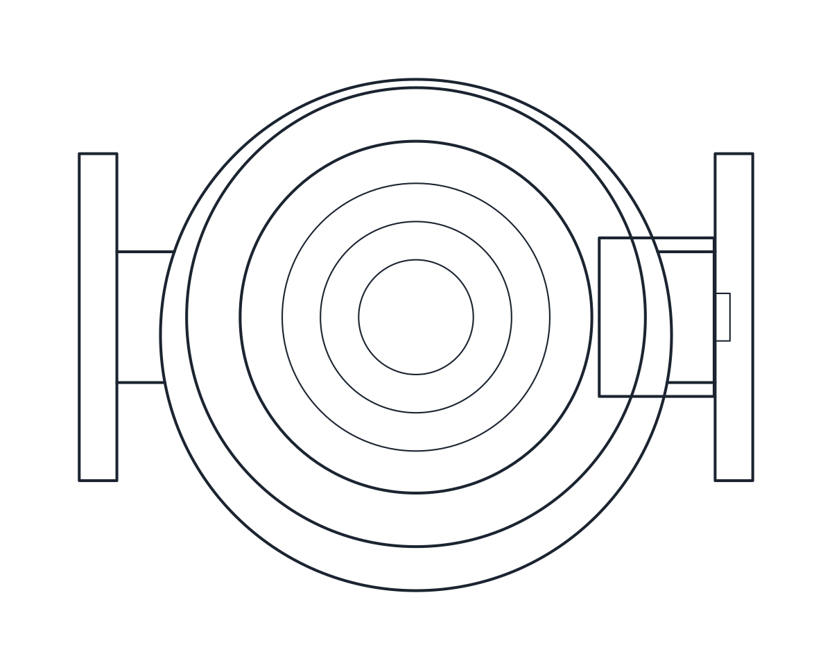
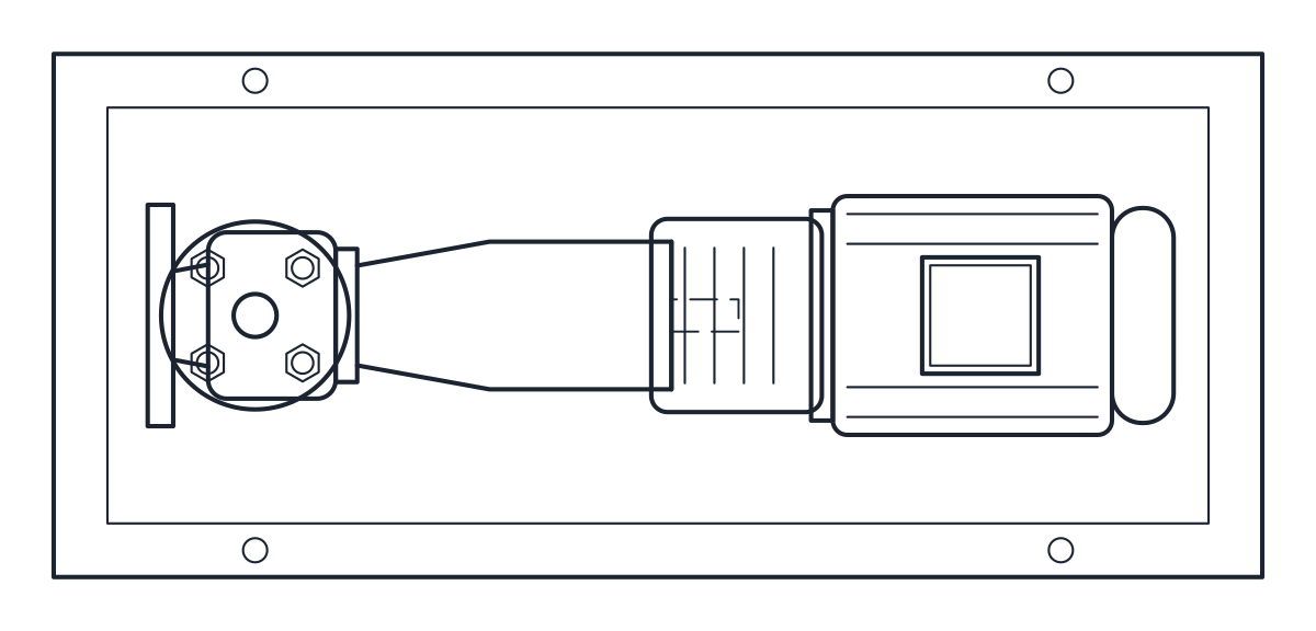
The elevation shows the relief valve at the front, the pump body with its port, the bell housing and the finned motor with its fan cowl and terminal box. The plan shows the same parts from above, with the ports on the sides of the pump body and the motor feet as hidden lines on layer A-HIDN. The block is 640 x 178 x 238 mm.
Using the gear pump block for oil and viscous fluids
Gear pumps suit oils and other clean viscous fluids. Place the block on a base or a skid, bring the suction to the port on one side and the discharge to the other, and keep the relief valve end accessible for adjustment. For a pump without an electric motor, see the diaphragm pump block. On a P&ID or a hydraulic diagram, see the pump symbol page, and draw the motor with the motor symbol.