Submersible Pump CAD Block
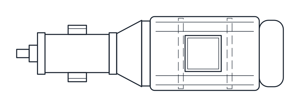
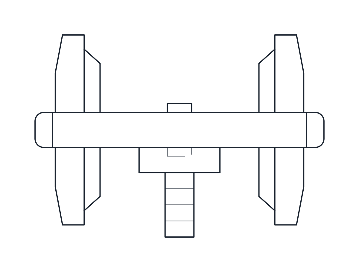
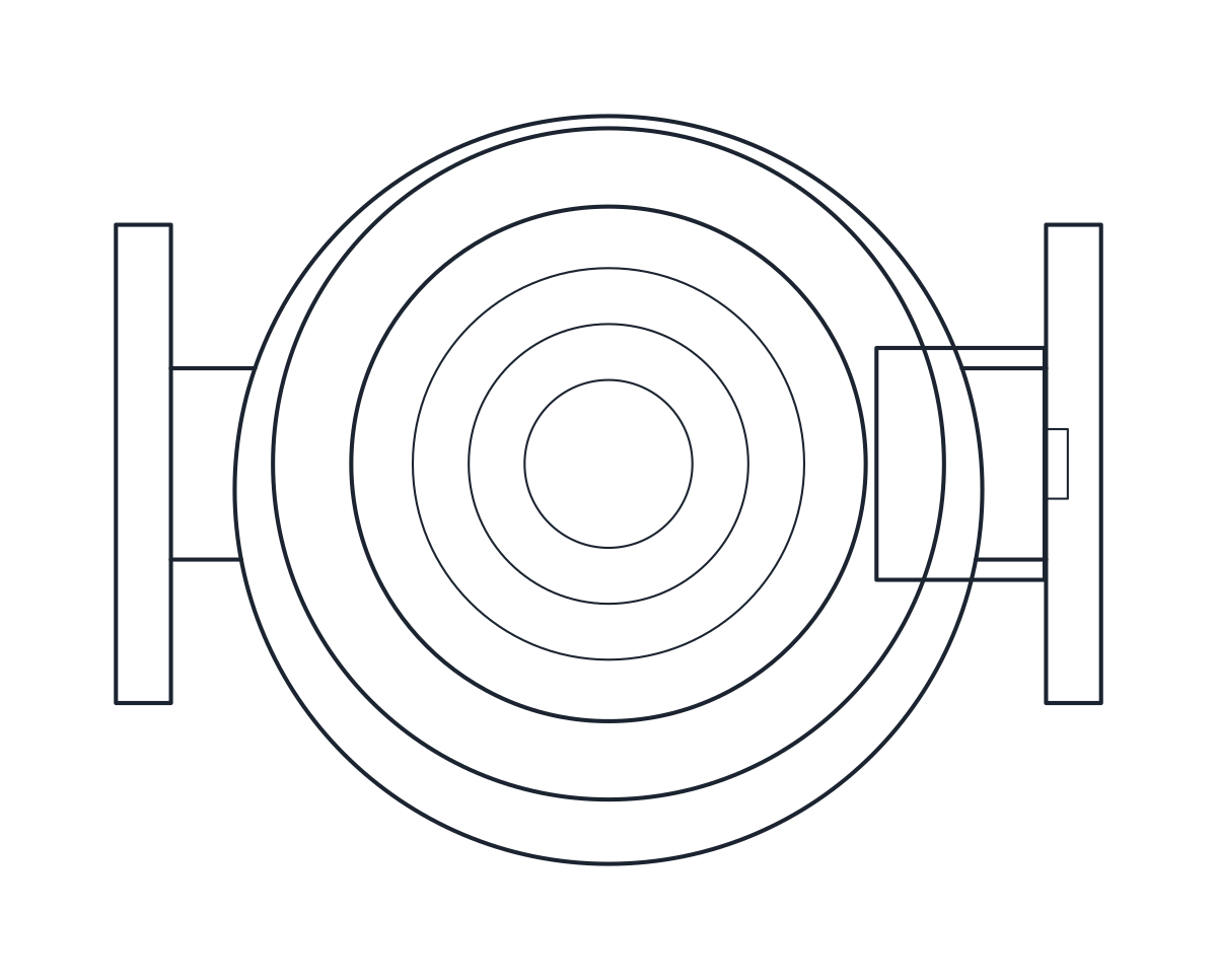
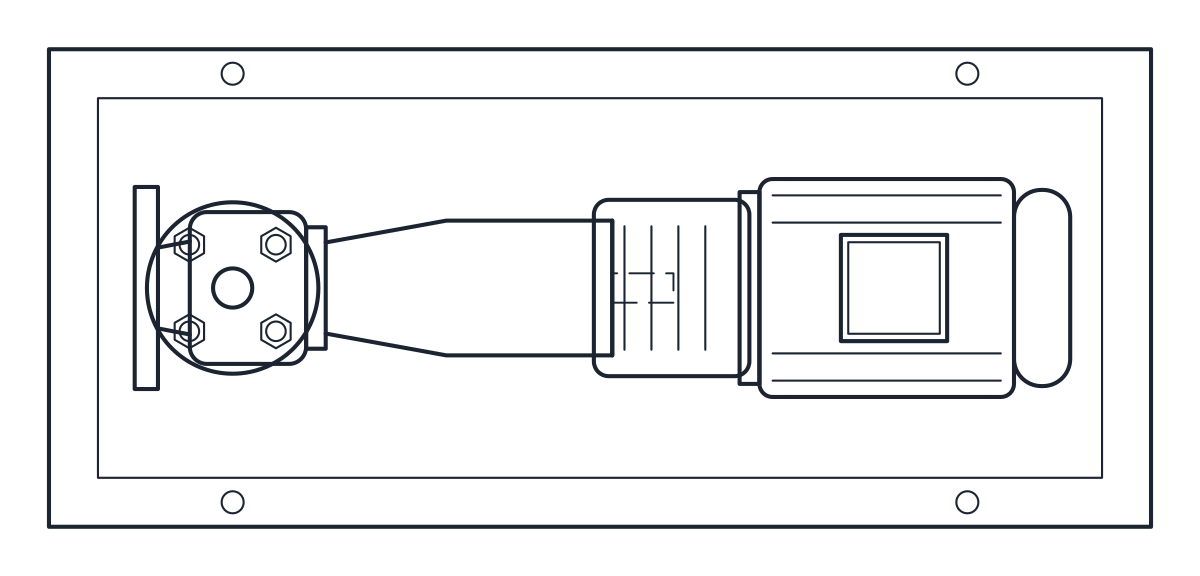
Small submersible drainage pump on a DN50 duckfoot bend, 436 mm long and 338 mm high.
Submersible drainage pump with DN50 duckfoot bend and guide hoop
- Units
- Millimetres (INSUNITS 4), drawn at paper size
- Formats
- DWG 2010 · DXF R2010
- Opens in
- AutoCAD and AutoCAD LT 2010 or later, BricsCAD, ZWCAD and DraftSight. The DXF opens in most CAD programs.
- Views
- Plan view + Front elevation
- License
- Free for personal and commercial projects. License
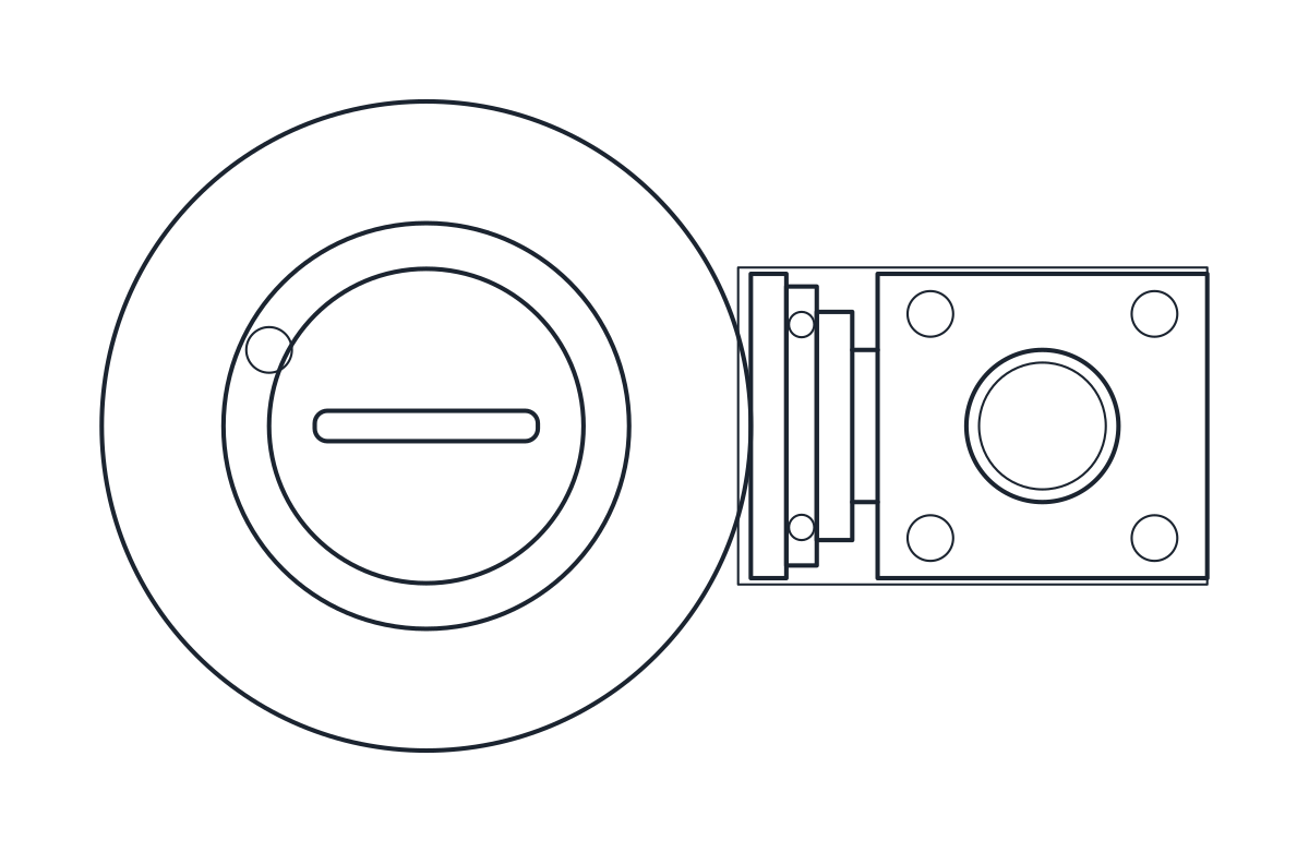
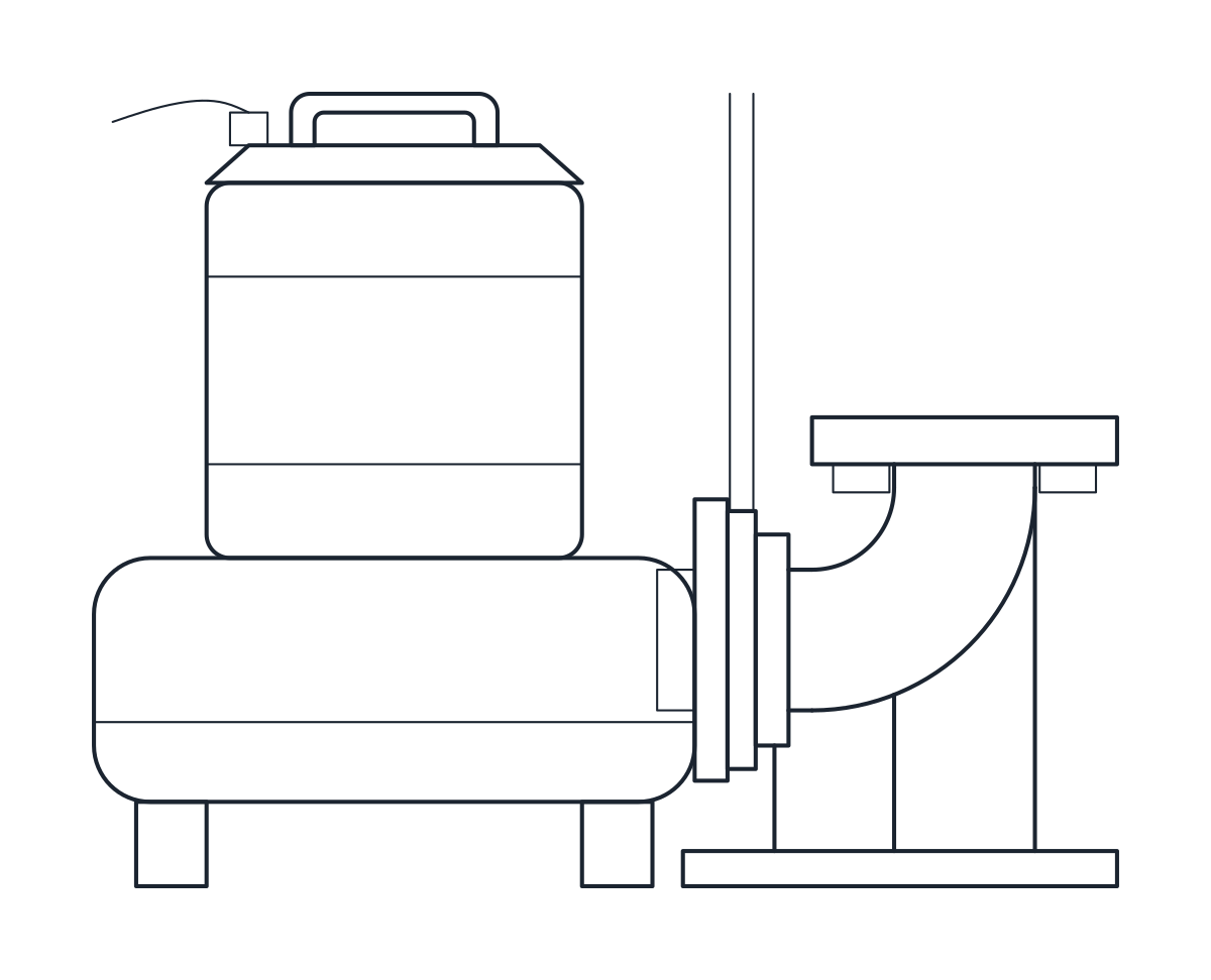
This download holds a small submersible drainage pump on a DN50 duckfoot bend, or auto-coupling, with a guide hoop. It is the stationary wet installation used in sumps and pump pits. The pump comes as a plan block and an elevation block in millimetres at full size, in a DWG for AutoCAD 2010 and later and in a DXF.
Submersible pump DWG dimensions
The measurements come from the installation drawing of a typical catalogue pump, so check them against the drawing of the pump you install.
- Overall length 436 mm and pump height 338 mm.
- Pump axis 128 mm from the left edge and 148 mm from the guide.
- Duckfoot bend DN 50/50: discharge flange 200 mm above the floor, outlet axis 105 mm above the floor, base 185 x 125 mm.
The plan is drawn 256 mm deep. The reference drawing gives 270 mm, which includes parts not drawn here, likely the cable and the handle. The anchor bolts under the floor are not drawn. The split of height between volute, motor and top cover and the shape of the bend are representative.
Submersible pump drawing in plan and elevation
The elevation shows the pump with its volute, motor and handle, the guide hoop hooked over the guide, and the duckfoot bend fixed to the floor with its flange on top. The plan shows the round pump and, beside it, the square base and flange of the bend. The outlines are on layer M-PUMP and the detail on M-PUMP-DETL.
Using the submersible pump block in a sump
Place the duckfoot base on the floor of the pit and run the guide up to the cover, so the pump can be lowered and lifted without anyone entering the sump. The discharge pipe rises from the flange at 200 mm. Draw the pit large enough for the pump plus the guide and the level switches you use. For a dry-installed pump outside the pit, see the end suction pump block, and on a P&ID use the pump symbol.