Gantry Crane CAD Block
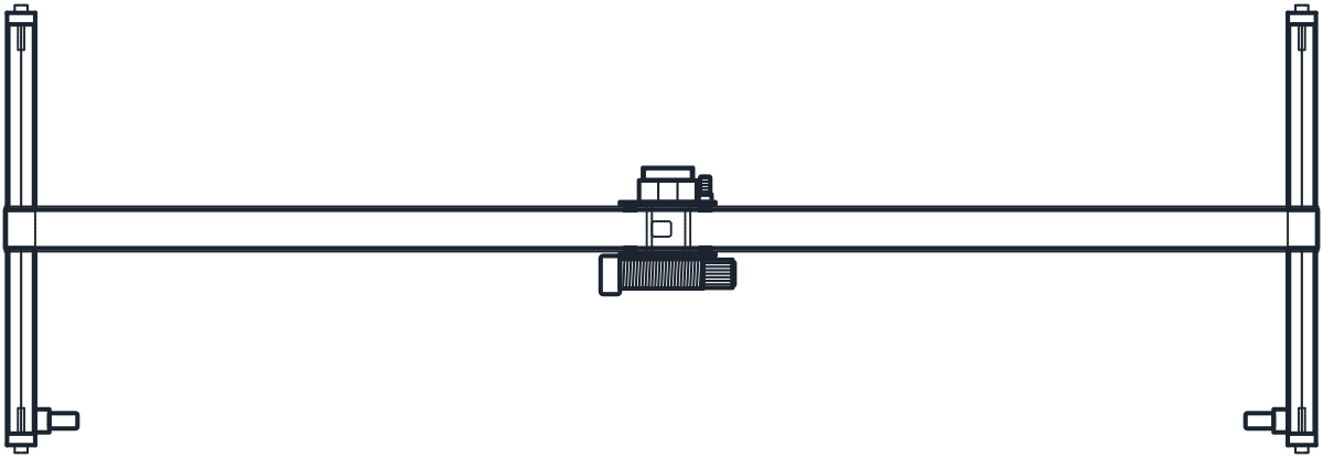
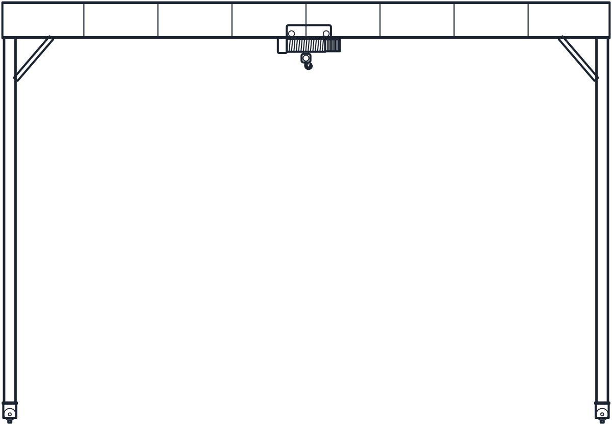
Single girder gantry crane of 10 m span with A-frame legs on floor rails and the hook at 6000 mm.
Single girder gantry crane, 10 m span, A-frame legs on floor rails
- Units
- Millimetres (INSUNITS 4), drawn at paper size
- Formats
- DWG 2010 · DXF R2010
- Opens in
- AutoCAD and AutoCAD LT 2010 or later, BricsCAD, ZWCAD and DraftSight. The DXF opens in most CAD programs.
- Views
- Plan view + Front elevation
- License
- Free for personal and commercial projects. License
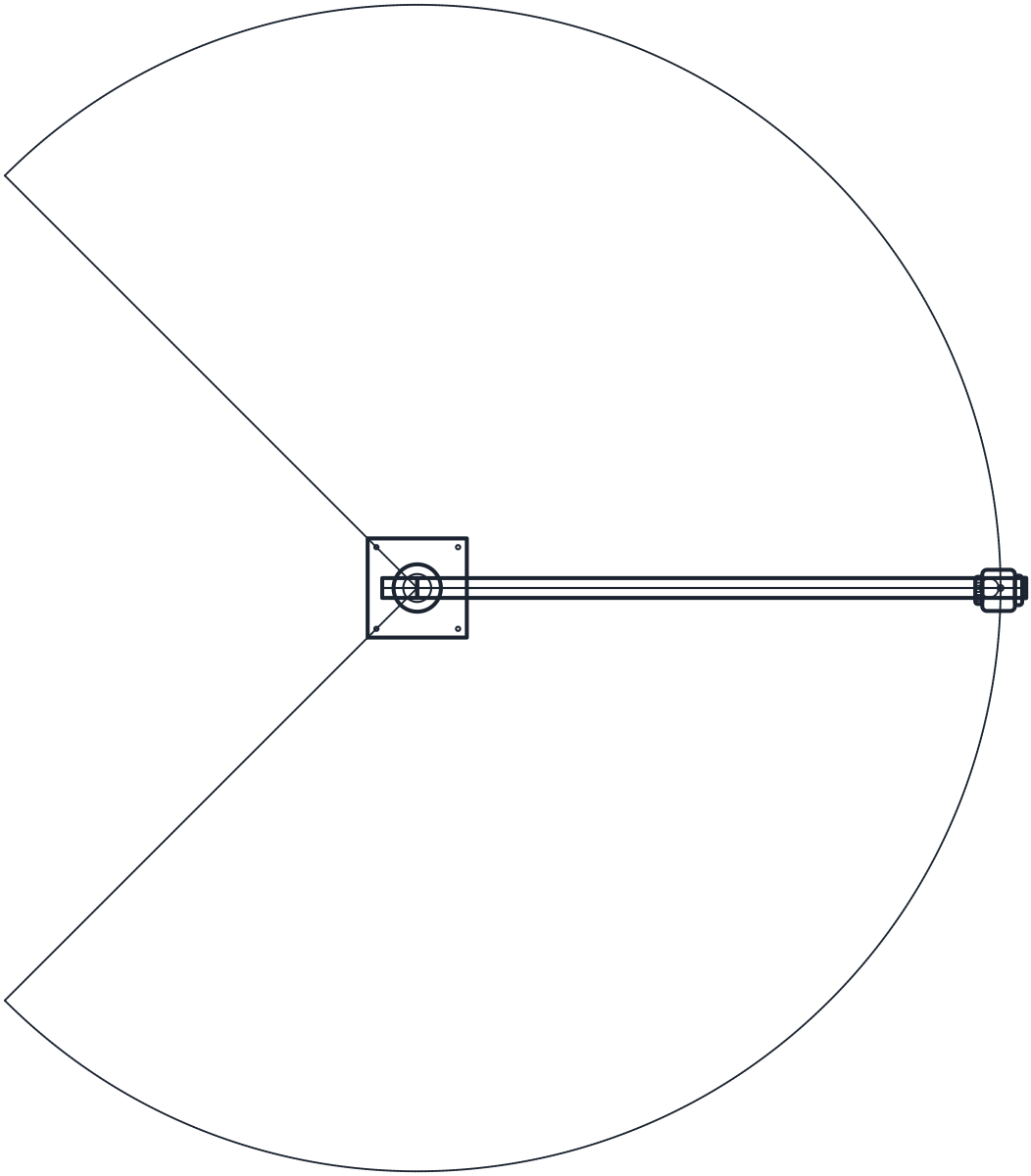
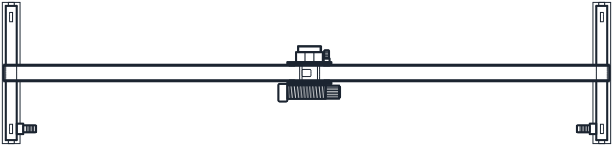
This download has one gantry crane block: a single girder full gantry with a 10 m span and A-frame legs that travel on floor rails. It comes in DWG and DXF with a plan and an elevation in millimetres, as IND_SINGLE_GIRDER_GANTRY_CRANE_10M_PLAN and IND_SINGLE_GIRDER_GANTRY_CRANE_10M_ELEV.
Gantry crane CAD block dimensions
The gantry is drawn at a 10 m span with the hook at 6000 mm. Both values sit inside the ranges that suppliers of single girder gantry cranes list, with spans of 4 to 35 m and 6 m among the usual lifting heights. No single public data sheet gives span, height and end carriage size for a 10 m gantry, so the 3000 mm wheelbase, the 3500 mm end carriages, the 200 mm wheels, the 600 mm box girder and the leg section are representative. Use the block as a layout drawing and take the real sizes from the crane builder.
Single girder gantry crane drawing in plan and elevation
The elevation looks along the rails, so the A-frame legs show edge-on, with knee braces where they meet the girder. The plan shows both legs of each frame and the end carriages on the rails at each side of the span. The hoist is the same monorail wire rope hoist as in the hoist CAD blocks, with its hook 520 mm below the bottom flange of the girder.
Using the gantry crane block in a yard or workshop
A gantry crane needs no runway beams on the building, because it travels on rails set in the floor. That makes it a common choice for open yards and for workshops whose structure cannot carry a crane. In the plan, keep the full travel along both rails clear, and keep the space between the legs free for the loads and the hook. Compare it with the overhead crane block when you weigh a runway against floor rails, and with the jib crane block when only one workstation needs lifting.
The rails, their foundations and the power feed are not part of the block. Add them from the data of the crane builder, who also sets the wheel loads that the floor has to carry.